
Installation guide

iNSTALLATiON MANUAL
(((( .................................................................................................. .........
Risk of fire or electrical shock exists if an
incorrect size range cord kit is used or the Installation Manua!
or strain relief clamp are disregarded,
Do not loosen the nuts which secure the factory-
installed range wiring to the terminal block while connecting
range, Electrica! Nilure or toss of" electrical connection may
Occur.
ELECTRICAL SNOCR NAZARD
* Electrical ground is required on this range,
* Do not connect to the electrical supply until range is permaneNly
grounded.
* DISCONNECT POWER TO THE CIRCUIT BREAKER
OR FUSE BOX BEFORE MAKING THE ELECTRICAL
CONNECTION.
* This range must be connected to a grounded, metallic,
permanent wiring system or the grounding connector of the
power cord should be connected to the grounding terminal or
wire lead on the range.
* Failure to heed these warnings could result in a fire, personal
injury or electrica! shock.
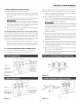
208/240 VOlT CONNNCTION INSTNUCTION$
The range can be set %r 208V or 240V. The voltage setting %r your
range is pie-set at 240V from the factory. Follow these steps to
change the voltage setting.
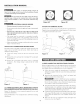
t Locate the voltage switch on the lower back side of the
range.
2 Remove the screw and rotate the switch plate 180_as indicated
in the Figure 3.
3 Reinsert the switcl_ plate and replace screw as indicated
in Figure 4. The voltage setting is indicated by the visible
marking.
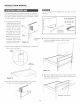
3 & 4oWINN ELECTRICAL WALL RECEPI"ACLE TYPN$ &
NNCONMNNDND NOUNYING ONINNTATION ON WALL
Figure 5A illustrates 4-wire receptacle required for new and
remodeled installations.
Figure 5B illustrates 3-wire receptacle that is allowed _br existing
installations,
4-wire wall receptacle (14-50%
Figure 5A
3-wire wall receptacle (10-50R)
Figure 5B
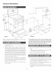
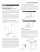
ACCESS TO TNNNIlNAL BLO¢I{
Loosen screw on rear access cover and pull down as illustrated in
Figm'e 6 to access terminal block wiring connection. 7ib close, retarn
to original location and secure screx_.
strain relief clamp
4
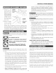
4-WINN CONNECTION INSTNUCTmON$oFIGUNN 8
Before wiring the range, re_ Jew the suggested power source location
drawing in Figure 2. If connecting to a 4-wire electrical system for a
new branch-circuit or mobile home use a 4-',_ire connection.
t Follow the power supply kit manufacturer's Installation
Instructions supplied with the strain relief clamp and insta!l.
See Figure 7.
2 Insert the end connectors for line 1, line 2 and neutral and
tighten securely to the terminal block.
DO NOT LOOSEN the fz_ctory installed nut
connections which secure the range wiring to the terminal
block. Electrical fzdNre or loss of electrical connection may
occur if these 3 nuts are loosened or removed.
3 You must disconnect the ground strap. Remo*e the fz_ctory
installed ground screw and plate to release the copper ground
strap from the frame of the range. Cut and discard the copper
ground strap and plate. KEEP the ground screw.
4 Connect the green ground wire lead with the eyelet to the frame
of the range with the ground screw using the same hole in the
frame where the ground screw was originally installed. See
Figure 8.
5 Make sure all screws are tightened securely and replace the
rear access cover. See Figure 6.