
Installation guide
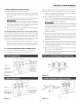

3oWINg CONNNCTION INSTNUCTmONS
For existing installations ONLY, refer to Figure 9.
t Follow the power supply kit manufacturer's Installation
Instructions supplied with the strain relief clamp and install.
See Figure 7.
2 Insert the end connectors fbr line 1, line 2 and neutral and
tighten securely to the terminal block. See Figure 7.
DO NOT LOOSEN the factory installed nut
connections which secure the range wiring to the terminal
block. Electrical failure or loss of electrical connection may
occur if these 3 nuts are loosened or removed.
3 Make sure all connections are tightened securely and replace
the rear access cover. See Figure 7.
GROUND|NG |NSTRUCT|ONS_ ONLY 3_W|RE CONNECT|ONS:
A ground strap is installed on this range which connects the center
terminal of the neutral terminal block to the range chassis. The
ground strap is connected to the range by the center, lowest screw.
See Figm*e 9. The ground strap must not be removed unless Nation,d,
State or Local Codes do not permit use of a ground strap.
Note: tf the ground strap is removed tbr any reason, a separate
ground wire must be connected to the separate ground screw
attached to the rauge chassis aud to an adequate ground source.
3 & 4oWINN PENN&NNNT WINN CONNNCTION$
3-_ire permanent connection - follow steps 1, 2 and 5 belo_.
4-wire permanent connection - fbllow a!l steps below.
mNSTALLATmON MANUAL
Befbre wiring the range, re_ ie_ the suggested power source location
drawings in Figure 2. If connecting to a 4-wire electrical system:
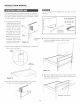
i Follow the manufacturer's Installation Instructions supplied
with the strain relief clamp and install.
2 Strip insulation away fi*om the ends of the permanent wiring
for line 1, line 2 and neutral; also strip ground wire on 4-wire
connections. Tighten all 3 or 4-wire leads to the terminal block.
Follow wire locations shown in Figure 10.
DO NOT LOOSEN the factory installed nut
connections which secure the range wiring to the terminal
block. Electrical failure or loss of electrical connection may
occur if these 3 nuts are loosened or remo_ ed.
Note: For 3-wire permanent connection skip steps 3 and 4 and
continue with step 5.
3 Disconnect the ground strap. Remoxe the factory installed
ground screw and plate to release the factory installed copper
ground strap from frarne of the range. Cut and discard the
copper strap from the terminal block. KEEP the ground screw,
ground plate and go to step 4.
4 Connect the green ground wire lead to the frame of the range
using the ground screw and plate as shown in Figure 11.Be sure
to install using the same hole in the frame where the ground
screw was originally installed.
5 Make sure all connections are tightened securely and replace
the rear access coxer. See Figure 7.
Note: Non-terminated field wire compression connections must
be set at approximately 90 in./lbs.
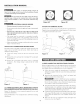
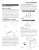
Connect {_ne
1 here
Discard ground strap
and ground plate
Connect green insulated
copper grourld wire with
ground screw here
Figure 8 _r "
terminal block
Nete: Install strain relief
c_amp Center or white
wire must always be
Connect attached to the center
terminal on block¸
Connect neutral (white or
center) here
A user supplied strain
relief clamp must be
rlstalled at this
location It requires 1
s/u-inches (35 cm}
diameter cord kit hole
\\\\
\'\\
Figure t O
Connect E_ne
1 here
Ground slra
Note: install strain relieI
clamp Center must
always be attached to the
center terminal on block
Figure 9
Connect neutral here
A user supplied strain relief
clamp must be installed at
diameter cord kit hole
\\\\\,
wire lead