
Installation guide

NORMALmNSTALLATmONSTEPS
ANTB-TmPBRACKET mNSTALLAT|ON |NSTNUCTmON$
iMPORTANT SAFETY WARNmNG
To reduce the risk of tipping of the range, the range must be secured
to the floor by properly installed Anti-Tip bracket and screws packed
with the range. Failure to install the Anti-Tip bracket ",_ill allow the
range to tip over if excessive weight is placed on an open door or if
a child climbs upon it. Serious injury might result fi'om spilled hot
liquids or from the range itself.
If range is ever mo_ed to a different location, the Anti-Tip bracket
must also be moved and installed with the range. Instructions are
provided fbr installation in wood or cemeN fz_stened to either the floor
or wall. When installed to the wall, make sure that screws completely
penetrate dry wall and are secured in wood or metal. When fastening
to the floor or wall, be sure that screws do not penetrate electrical
wiring or plumbing.
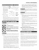
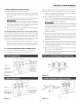
"t LGCATE THE BRACKET - UStNG THE TEMPLATE
The bracket may be located on either the left or right side of the
range. Use the information below to locate the bracket if template
is not available.
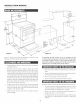
iNSTALLATiON MANUAL
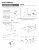
2 DNmLLP|LOT HOLES AND FASTEN BNACN:NT
Drill a l/s-inch pilot hole where screws are to be located. If bracket
is to be mounted to the wall, drill pilot hole at an _pproximate 20
degree downward angle. If bracket is to be mounted to masonry or
ceramic floors, drill a 5/32-inch pilot hole 1 3/4 inches deep. The
screws provided m_3" be used in wood or concrete material Use a
5/16-inch nut-driver or flat head screwdriver to secure the bracket
in place.
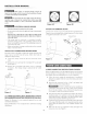
leveling leg --
leveling leg
Mark the floor or wall where left or right side of the range will be
located. If rear of range is against the wall or no further than 1 1/4-
inches from wall when installed, you rn_y use the wall or floor mount
method. If molding is installed and does not allow the bracket to fit
flush against the wall, remo're molding or mount bracket to the floor.
For wall mount, locate the bracket by placing the back edge of the
template against the rear wall and the side edge of template on the
mark made referencing the side of the range. Place bracket on top
of template and mark location of the screw holes in wall. If rear of
range is f;arther than 1 1/4-inches from the wall when installed, attach
bracket to the floor. For floor mount, locate the bracket by placing
back edge of the template where the rear of the range will be located.
Mark the location of the screw holes, shown in template.
wall
lloor mount _ Anti-Tip bracket
F_gure t 7
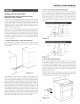
3 LEVEL AND POS|T|ON RANGE
Level rm_ge by a_[insting the (4) le_ cling legs with a wrench. Note:
A minimum clearance of 1/8-inch is required between the bottom
of the range and the leveling leg to allow room for the bracket. Use
a level to check your adjustments. Plug range into properly prepared
electrical receptacle or if hard wired, check that it was completed
properly. Check floor condition fbr evenness and stability. Slide
range back into position.
Visually check that rear leveling leg is inserted into and fully
secured by the Anti-Tip bracket by looking underneath the range
with a flashlight and carefully attempt to tilt it forward.
H_kge Slide -_
Figure t8
7