Residential Energy Storage Unit For Photovoltaic Systems RESU3.3 (R4863P3S) RESU6.5 (R48126P3S) RESU10 (R48189P3S) RESU Plus Installation Manual Revision 2.
About this manual This manual describes how to install LG Chem’s RESU® battery pack. Read this manual before you attempt to install the product, and follow the instructions throughout the installation process. If you are uncertain about any of the requirements, recommendations, or safety procedures described in this manual, contact LG Chem immediately for advice and clarification. The information included in this manual is accurate at the time of publication.
Contents Contents 3 1 Safety 6 1.1 Symbols on product labels . . . . . . . . . . . . . . . . . . . . . . . . . . 6 1.2 Safety instructions . . . . . . . . . . . . . . . . . . . . . . . . . . . . . . . 7 1.2.1 General safety precautions . . . . . . . . . . . . . . . . . . . . . 7 1.2.2 Battery handling guide . . . . . . . . . . . . . . . . . . . . . . . . 8 Response to emergency situations . . . . . . . . . . . . . . . . . . . . . . 8 1.3.1 Leaking batteries . . . . . . . . . . . . . . . .
Contents 4.3 Optional accessories . . . . . . . . . . . . . . . . . . . . . . . . . . . . . 22 4.4 Checks before installation . . . . . . . . . . . . . . . . . . . . . . . . . . 22 4.5 Installation clearance . . . . . . . . . . . . . . . . . . . . . . . . . . . . . 25 4.6 Securing battery pack to wall . . . . . . . . . . . . . . . . . . . . . . . . 25 4.7 Cable connections . . . . . . . . . . . . . . . . . . . . . . . . . . . . . . . 27 4.7.1 Connecting ground wire . . . . . . . . . . . . .
Contents 7.3 Shutting down battery pack . . . . . . . . . . . . . . . . . . . . . . . . . 44 8 Troubleshooting 45 9 Firmware Update 46 9.1 Updating battery pack firmware . . . . . . . . . . . . . . . . . . . . . . 46 9.2 Updating RESU Plus firmware . . . . . . . . . . . . . . . . . . . . . . .
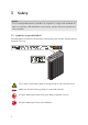
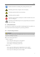
1 Safety NOTE To use rechargeable batteries, installers are required to comply with standard AS 4086.2 in Australia, VDE-AR-E2510-2 in Germany, and the domestic legislation in other countries. 1.1 Symbols on product labels The nameplate is attached to the left side of the battery pack, and the warning label is CO NN EC TIO NK IT O N O FF attached to the top. The voltage of this battery pack is strong enough to cause electric shock. Make sure that the battery polarity is connected correctly.
Safety Read the manual before installing and operating the battery pack. The battery pack is heavy enough to cause severe injury. The battery pack may leak corrosive electrolyte. The battery pack may explode. The battery pack should not be disposed of with household waste at the end of its working life. The battery pack should be disposed of at a proper facility for environmentally safe recycling. 1.
Safety – Do not allow the battery connectors to touch conductive objects such as wires. • Risks of electric shock – Do not disassemble the battery pack. – Do not touch the battery pack with wet hands. – Do not expose the battery pack to moisture or liquids. – Keep the battery pack away from children and animals. • Risks of damage to the battery pack – Do not allow the battery pack to get in contact with liquids. – Do not subject the battery pack to high pressures.
Safety 1.3.1 Leaking batteries If the battery pack leaks electrolyte, avoid contact with the leaking liquid or gas. Electrolyte is corrosive and contact may cause skin irritation and chemical burns. If one is exposed to the leaked substance, do these actions: Inhalation: Evacuate the contaminated area, and seek medical attention immediately. Eye contact: Rinse eyes with flowing water for 15 minutes, and seek medical attention immediately.
Safety 1.3.4 Damaged batteries Damaged batteries are dangerous and must be handled with extreme caution. They seems to be damaged, pack it in its original container, and then return it to LG Chem or your distributor. CAUTION such damage, immediately contact LG Chem for advice and information.
2 Product Introduction 2.1 Technical data 2.1.1 Dimensions and weight RESU3.3 RESU6.5 RESU10 RESU Plus Length 452 mm (17.80 in) 452 mm (17.80 in) 452 mm (17.80 in) 216 mm (8.50 in) Width 120 mm (4.72 in) 120 mm (4.72 in) 227 mm (8.94 in) 120.5 mm (4.74 in) Height 1 Weight 1A 402.5 mm (15.85 in) 655.5 mm (25.81 in) 484 mm (19.06 in) 156 mm (6.14 in) 31 kg (68.3 lb) 2 kg (4.4 lb) 52 kg (114.6 lb) 75 kg (165.
Product Introduction 2.1.2 Performance RESU3.3 RESU6.5 RESU10 Nominal voltage 51.8 V 51.8 V 51.8 V Operating voltage 42 to 58.8 V 42 to 58.8 V 42 to 58.8 V Nominal capacity 63 A·h 126 A·h 189 A·h Nominal energy 3.3 kW·h 6.5 kW·h 9.8 kW·h Standard power 1.1 kW 2.2 kW 3.3 kW Maximum power 3 kW 4.2 kW 5 kW Peak power for 3 seconds 3.3 kW 4.6 kW 7 kW Peak current for 3 seconds 78.6 A 109.5 A 166.7 A Maximum current 71.
Product Introduction 2.1.5 Environmental requirements Available operating temperature −10 to 45 °C (14 to 113 °F) Optimal operating temperature 15 to 30 °C (59 to 86 °F) Storage temperature −30 to 60 °C (−22 to 140 °F) Humidity 5 to 95% (non-condensing) Altitude Below 2000 m (6562 ft) 2.2 Features The RESU® battery pack has the following features: Energy storage unit: This battery pack is designed for domestic photovoltaic system compatibility.
Product Introduction 2.3 RESU lineup There are three RESU battery pack models. CONN ECTIO N KIT ON F OF RESU3.3 RESU6.5 RESU10 For details about these models, see Technical data on page 11. 2.4 RESU Plus The RESU battery pack can be used in combination of up to 2 units. • RESU3.3 + RESU3.3 • RESU3.3 + RESU6.5 • RESU3.3 + RESU10 • RESU6.5 + RESU6.5 • RESU6.5 + RESU10 • RESU10 + RESU10 A unit of RESU Plus, which is sold separately, is required to install two RESU battery packs.
Product Introduction 1) 1st battery pack 2) 2nd battery pack 3) RESU Plus 4) Inverter Use this procedure to install two battery packs using the RESU Plus. 1. Secure the RESU Plus to the wall. 2. Secure two battery packs to the wall. 3. Connect power and network cables to the RESU Plus. 4. Connect the power and network cables to the inverter. 5. Connect the power and network cables to the battery packs.
3 Installation Prerequisites 3.1 Installation materials These installation materials shall be prepared by installers. • Charging cable • Network cable • Ground wire • RJ45 plug • Silicone sealant or putty NOTICE Make sure that the cross-sectional area of charging cables is 33 to 50 mm2 . 3.2 Installation location Make sure that the installation location meets the following conditions: • The building is designed to withstand earthquakes.
Installation Prerequisites operate is 15°C to 30°C. Frequent exposure to harsh temperatures may deteriorate the performance and lifetime of the battery pack. 3.3 Tools These tools are required to install the battery pack. Torque screwdriver Phillips-screwdriver bit Hex-key bit Phillips-head screwdriver Flat-head screwdriver Torque wrench Wire stripper Cable crimper Voltmeter Tape measure Drill Sealant gun Use properly insulated tools to prevent accidental electric shock or short circuits.
Installation Prerequisites 3.4 Safety gear Wear the following safety gear when dealing with the battery pack. Installers must meet the relevant requirements ofinternational standards, such as IEC 60364 or the domestic legislation. Insulated gloves Safety goggles Safety shoes 3.5 Making network cable Use this method to make a network cable, which is to be connected between the battery pack and the inverter or the RESU Plus. 1. Cut network cable to the needed length. 2. Strip 2.
Installation Prerequisites 8) Brown 5. Bring the sorted wires together, and trim them to about 1.4 cm in length. 6. Hold the RJ45 plug with the copper contacts facing up, and insert the wires into the plug, making sure that they stay aligned and each color goes into its appropriate channel. 7. Put the plug into a cable crimper and squeeze the handles thoroughly. 8. If available, use a LAN cable tester to see if the cable is faulty. Repeat these steps for the other end of the cable.
4 Battery Pack Installation WARNING The battery pack is too heavy for one to carry. Make sure that two or more persons are available. 4.1 Unpacking Unpack the battery pack from its packaging. 1. Cut the packing tape and open the carton. 2. Remove the drill template. 3. Remove the honeycomb cushioning pads. 4. Pull out the battery pack and stand it upright. OFF CO NN EC TIO N KIT ON 20 Check if the battery pack is damaged.
Battery Pack Installation 5. All the other items are contained in a box in one corner of the carton. Take them out and check if any item is missing. See Package items on page 21. 6. Replace the honeycomb cushioning pads. Keep the carton for future storage or transportation. 4.2 Package items These items are included in the package. CON NEC TION KIT ON F OF Battery pack Cable grommets Screw anchors Screws Mounting brackets The table below lists the number of each item included.
Battery Pack Installation Large grommets for charging cables 2 Small grommets for other cables 3 Mounting brackets 2 M6 × 40 screw anchors 6 (2 as spare) M5 × 8 screws 4 Use only the parts included with the battery pack, except for the screw anchors, to ensure proper installation. If anything is damaged or missing, contact LG Chem or your distributor. 4.3 Optional accessories These baseplates and shelves are sold separately. Baseplate for RESU3.3 and RESU6.
Battery Pack Installation 1. Remove the top cover. Loosen the four hexsocket screws at each corner of the cover, and pull it up. 2. Make sure to set the SW select DIP switch to 00112 . See Configuring Battery pack on page 39. TIO EC NN CO NK NOTE O FF O N IT possible to measure the voltage of the batThe battery pack is designed to make it tery pack only if the SW select DIP switch is set to 00112 . 3.
Battery Pack Installation 6. Press the circuit breaker’s trip button. If the circuit breaker switch has not moved to the Trip position, do not use the battery pack. Contact LG Chem or your distributor. NK TIO EC NN CO IT ON OFF 7. Measure the voltage at the terminal block using a voltmeter. If the voltage is higher than 0 V, do not use the battery pack. Contact LG Chem or your distributor. NK TIO EC NN CO IT ON OFF 8.
Battery Pack Installation 4.5 Installation clearance 300 mm N TIO EC NN CO KIT 300 mm ON F OF N TIO EC NN CO KIT ON F OF 300 mm 300 mm 300 mm 300 mm 9 mm 300 mm 9 mm Make sure to leave a space of at least 9 mm between the battery pack and the wall. A clearance of at least 9 mm must be left around the battery pack for proper cooling. NOTICE Make sure that the battery pack is always exposed to the ambient air. The battery pack is cooled by natural convection.
Battery Pack Installation 1. Determine where the mounting brackets are to be placed using the drill template. 2. Drill holes in the wall for the M6 (0.25 in) screw anchors. The drilling depth should be at least 50 mm. 3. Drive the screw anchors through the mounting brackets into the holes. 4. Tighten the screws to a torque of 5 N·m. NOTE It is allowed to use any other type of fastening suitable for the wall material. 5. Remove the top cover.
Battery Pack Installation 6. There are screw holes for mounting brackets on the top of the both sides of the battery pack. NK TIO EC NN CO Drive the M5 screws through the mounting IT ON OFF brackets into the holes and tighten them to a torque of 5 N·m. 4.7 Cable connections WARNING Make sure that the inverter is turned off before connecting the battery pack to the inverter. 4.7.
Battery Pack Installation 4.7.2 Connecting network cable It is required for the battery pack to communicate with the inverter for proper operation. Connect a network cable between the battery pack and the inverter or RESU Plus. 1. The small grommet is too small for an RJ45 NK TIO EC NN CO plug to pass through. Without RJ45 plug at IT ON OFF the end, feed the network cable through a small grommet and then through the top of the small cable entries. 2.
Battery Pack Installation 4.7.3 Connecting power cables for RESU Plus NOTE Skip this task if the RESU Plus is not installed. NK TIO EC NN CO IT ON OFF To supply power to the RESU Plus for its operation, connect the provided power cables from the battery pack to the RESU Plus. 1. Insert the connector of the power cable into the power connector. 2. Feed the power cable through the middle of the small cable entries and then through a small grommet 3. Push the grommet into the cable entry. 4.7.
Battery Pack Installation NOTICE Pay attention not to reverse polarity. Connection with reversed polarity causes severe damage to the battery pack. 2. Connect the charging cables to the terminal block. a) Remove the terminal cover plate, which is placed over the terminal block to protect NK TIO EC NN CO it. IT ON OFF b) Connect the negative cable (−) to the terminal on the left and the positive cable (+) to the one on the right. Tighten the hexsocket screws to a torque of 6 N·m.
Battery Pack Installation 4. Turn on the battery pack as described in Commissioning battery pack on page 43. 5. Replace the top cover and tighten the screws to a torque of 5 N·m.
5 RESU Plus Installation NOTE Skip this chapter if only one battery pack is to be installed. 5.1 Unpacking Unpack the RESU Plus from its packaging. 1. Cut the packing tape and open the carton. 2. Remove the cover of the inner box. 3. Pull out the RESU Plus. 4. Check if the RESU Plus is damaged. 5. Keep the carton for future storage or transportation. 5.2 Package items These items are included in the package.
RESU Plus Installation The RESU Plus has glands and grommets attached to their own places. The table below lists the number of each item included. Power cables 2 Anchor bolts 2 5.3 Securing RESU Plus to wall Secure the RESU Plus to a wall to prevent it from moving. 1. Remove the front cover of the RESU Plus. Loosen the screws at each corner of the cover and pull it up. 2. Loosen the screws at each corner of the metal plate that supports the circuit board.
RESU Plus Installation 3. Pull up the circuit board to remove it. NOTICE To prevent the circuit board from being damaged or soiled, keep it in a safe place until it is replaced. 4. Determine where the anchor bolts are to be placed. 5. Drill holes in the wall for the M8 (0.3 in) anchor bolts. The drilling depth should be 50 mm at least. 6. Drive the anchor bolts into the wall holes through the screw holes at the upper left and the lower right of the rear of the RESU Plus. 7.
RESU Plus Installation 5.4.1 Connecting charging cables 1. Loosen the sealing nuts of the large glands. 2. Feed charging cables through the large glands, and connect each charging cable to its corresponding terminal. Use the terminal block at the lower left for the first battery pack, the one at the lower right for the second battery pack, and the one at the upper for the inverter. 3. Tighten the sealing nuts firmly. 4.
RESU Plus Installation 5.4.2 Connecting ground wires Grounding between the battery pack and the inverter is not mandatory but recommended. 1. Loosen the sealing nuts of the small glands that are closest to the edges. 2. Feed ground wires through the glands. 3. Connect each ground wire to its corresponding ground point. Use the ground point at the lower left for the first battery pack, the one at the lower right for the second battery pack, and the one at the upper for the inverter. 4.
RESU Plus Installation 3. Connect each power cable to its corresponding terminal block. Use the terminal block at J4 the left for the first battery pack and the one J9 at the right for the second battery pack. Connect the negative line (−) to the terminal on the left and the positive line (+) to the one on the right. 4. Tighten the sealing nuts firmly. 5.4.4 Connecting network cables It is required for the battery packs to communicate with the inverter via the RESU Plus for their proper operation. 1.
RESU Plus Installation 5.5 Finalizing installation Follow these steps to finalize the installation. 1. Check if the configuration switches on the RESU Plus and both battery packs are set properly, referring to Configuring RESU Plus on page 41 and Configuring Battery pack on page 39. 2. Turn on the battery pack as described in Commissioning battery pack on page 43. 3. Replace the front cover and tighten the screws to a torque of 1 N·m.
6 Configuration Switches The RESU battery pack and RESU Plus have inside DIP switches and rotary switches, which must be set correctly for proper communication with the inverter. 6.1 Configuring Battery pack Remove the switch cover by pulling it up to expose the circuit board. ON OFF Switch number Type Label Default 1 DIP SW select 00002 2 DIP Cell select 002 3 Rotary CAN_H 4 4 Rotary CAN_L 5 5 Rotary GND 2 6 DIP Term Res 112 6.1.
Configuration Switches stalled, they must be connected to a RESU Plus. In the case, they are indirectly connected to the inverter via the RESU Plus, and thus the switch must be set to 00102 . The number of battery packs Value 1 00111 2 00102 Setting 6.1.2 Setting for battery cell type Make sure that the Cell select DIP switch is set to 002 . 6.1.3 Settings for CAN bus pins Make sure that the CAN_H rotary switch is set to 4.
Configuration Switches 6.2 Configuring RESU Plus SW select CAN_H CAN_L GND TermRes Switch number Type Label Default 1 DIP SW select 00112 2 Rotary CAN_H 4 3 Rotary CAN_L 5 4 Rotary GND 2 5 DIP Term Res 112 6.2.1 Setting for communication interface Make sure that the SW select DIP switch is set to 00112 . 6.2.2 Settings for CAN bus pins See the section of the same title on page 40. 6.2.3 Setting for terminal resistors Make sure that the TermRes DIP switch is set to 112 .
7 Commissioning 7.1 Status indicators 7.1.1 Battery pack O FF O N CONN ECTIO N KIT There are four LED indicators on the front of the battery packs to show its operating status. ON: This indicator stays on while the battery pack is supplied with power for operation. Charging: This stays on while the battery pack is charging. Discharging: This stays on while the battery pack is discharging. Warning: This comes on when the battery pack is in a warning state. See Troubleshooting on page 45.
Commissioning 7.1.2 RESU Plus There are four LED indicators on the front of the RESU Plus to show its operating status. ON: This indicator stays on while the battery pack is supplied with power for operation. Pack 1: This stays on while the first battery pack is online with the RESU Plus. Pack 2: This stays on while the second battery pack is online with the RESU Plus. Fault: This comes on when one or both battery packs are in a warning or fault state. See Troubleshooting on page 45.
Commissioning 1. Move the circuit breaker switch to the ON position to turn on the battery packs. If two battery packs are installed, both must be turned on at an interval of less than 30 seconds. 2. On both battery packs, make sure that the ON indicator is on. If it stays off, do not use the battery pack. Contact LG Chem or your distributor. 3. On the RESU Plus, make sure that either or both of the Pack 1 and Pack 2 indicators are on.
8 Troubleshooting Check the indicators on the front to determine the state of the battery pack. A warning state is triggered when a condition, such as with voltage or temperature, is beyond design limitations. The battery pack’s BMS periodically reports its operating state to the inverter. When the battery pack falls outside prescribed limits, it enters a warning state. When a warning is reported, the inverter immediately stops operation.
9 Firmware Update It is possible to update the BMS firmware. Use a memory card to update it. A new firmware may be available from LG Chem website or your distributor. Prepare a memory card with these properties. • The capacity of the memory card must not be greater than 32 GB. • The memory card must be formatted in FAT16 or FAT32. • It must have only one firmware file in the root directory. For details about supported memory cards, see Supported Memory Cards on page 52. 9.
Firmware Update 4. Press and hold the update button beside the memory card slot for more than 3 seconds. NN CO NK TIO EC O FF O N IT 5. The LED indicators flash in cycles for 1 minute at most until the firmware update is complete. Only the ON indicator comes on when the firmware update is successful. If it fails, the Warning indicator comes on for two seconds. Check the memory card and try again. If it persistently fails, contact LG Chem or your distributor. 6. Remove the memory card.
Firmware Update 9.2 Updating RESU Plus firmware 1. Turn off the inverter. 2. Open the flap on the left side of the RESU Plus. 3. Insert the memory card into the memory card slot. 4. Press and hold the update button beside the memory card slot for more than 3 seconds. 5. The LED indicators flash in cycles for 1 minute at most until the firmware update is complete. Only the ON indicator comes on when the firmware update is successful. If it fails, the Fault indicator comes on for two seconds.
10 Warranty LG Chem protects this product under warranty when it is installed and used as detailed in this manual. Violating the installation procedure or using the product in any way not described in this manual immediately voids all warranties on the product.
11 Certifications Battery pack safety CE, FCC, RCM, TUV (IEC 62619), UL 1973 Battery cell safety UL 1642 UN number UN 3480 Hazardous materials classification Class 9 UN transportation testing requirements UN 38.
A Compatible Inverters For information about inverters that are compatible with the RESU Plus battery pack, visit LG Chem’s website. • http://www.lgesspartner.com/au • http://www.lgesspartner.com/de • http://www.lgesspartner.
B Supported Memory Cards Most memory cards can be used for firmware update. However, some memory cards may not be supported, depending on manufacturers and models. These memory cards are tested and guaranteed to work by LG Chem.
Keep this manual for later use.