SERVICE MANUAL CODE: 00ZMXLCX2/S1E DIGITAL FULL COLOR MULTIFUNCTIONAL SYSTEM OPTION LARGE CAPACITY TRAY MODEL MX-LCX2 CONTENTS [1] PRODUCT OUTLINE. . . . . . . . . . . . . . . . . . . . . . . . . . . . . . . . . . . . . . . . 1-1 [2] SPECIFICATIONS . . . . . . . . . . . . . . . . . . . . . . . . . . . . . . . . . . . . . . . . . . 2-1 [3] UNPACKING AND INSTALLATION * For unpacking and installation, refer to the installation manual( [2] ). [4] EXTERNAL VIEWS AND INTERNAL STRUCTURES . . . . . . . . . .
CONTENTS [1] PRODUCT OUTLINE . . . . . . . . . . . . . . . . . . . . . . . . 1-1 [2] SPECIFICATIONS . . . . . . . . . . . . . . . . . . . . . . . . . . 2-1 [3] UNPACKING AND INSTALLATION * For unpacking and installation, refer to the installation manual( [2] ). [4] EXTERNAL VIEWS AND INTERNAL STRUCTURES 1. Motor, clutch, solenoid . . . . . . . . . . . . . . . . . . . . 4-1 2. PWB, sensor, switch, heater . . . . . . . . . . . . . . . . 4-2 [5] OPERATIONAL DESCRIPTION 1. Lift operation . . . . . . . . . . .
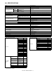
MX-LCX2 [1] PRODUCT OUTLINE Service Manual This model is a large capacity paper feed tray installed to the main unit. It stores 3,500 sheets, eliminating troublesome paper supply.
MX-LCX2 [2] SPECIFICATIONS Service Manual Model Transport reference Large capacity tray Center reference Domestic: Heater kit support Overseas: Service parts support Heat reserving heater Domestic Paper capacity Overseas Normal paper (64g/m2 ,17 lbs bond) Normal paper (80g/m2 ,21 lbs bond) 4000 sheets 3500 sheets Paper size/type/weight Paper size detection Paper type setting Paper size change system Factory setting of paper size Changeover by user Changeover by service man (Adjustment of guide and
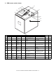
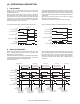
MX-LCX2 Manual [4] EXTERNAL VIEWS AND INTERNAL Service STRUCTURES 1. Motor, clutch, solenoid 4 3 5 No. 1 2 Parts Code Signal name Name Type Function/Operation Drives the paper feed, and the paper transport section. 1 LPFM LPFM Transport motor Brushless motor 2 LLM LLM Lift motor Brush motor 3 LTRC LTRC Transport clutch Controls ON/OFF of the transport roller. Lifts the paper feed table. 4 LPFC LPFC Paper feed clutch Controls ON/OFF of the paper feed roller.
2. PWB, sensor, switch, heater 14 13 12 15 11 16 7 17 9 10 8 Parts No.
[5] OPERATIONAL DESCRIPTION MX-LCX2 Service Manual 1. Lift operation When the main unit is turned ON, if the tray is at the lower limit position (lower limit sensor: LDD ON position), the lift motor is turned ON to lift the tray. When the paper presence/empty sensor (LPED) is turned ON within 800 pulses of the encoder signal from start of lifting up the tray, the lift motor is turned OFF to stop the tray, and the paper feed solenoid is turned ON to move down the pickup roller.
5 1 4 6 3 7 2 1 2 3 4 5 6 7 Paper feed roller clutch Take-up roller Paper feed roller Paper feed solenoid Transport clutch Transport motor Lift-up motor 3. Paper empty detection When the tray lifts and stops at the paper feed position and during paper feed operation, paper presence/empty is detected by the paper presence/empty sensor (LPED). When paper empty is detected in the tray during paper feeding, paper feeding is stopped.
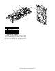
MX-LCX2 [6] DISASSEMBLY AND ASSEMBLY 2. EachManual unit removal Service A. Paper feed unit 1) Pull out the tray. 2) Open the upper cover, and remove three screws. 3) Remove the upper cabinet. 4) Disconnect the connectors (2 positions). 5) Remove the screw, and remove the paper feed unit. 1. Maintenance parts replacement procedures A. Paper feed roller 1) Pull the lever, and open the upper cover. 2) Remove the screw, and remove the sheet.
B. Paper feed tray C. Drive unit 1) Pull out the tray. 1) Remove the screw, and remove the rear cover. 2) Looser the stopper fixing screw (1) on the lower right side of the paper tray, evacuate the stopper not to function. 2) Remove the connectors (2 positions). 3) Remove the screw, and remove the drive unit. 3) 4) Remove the screws from the left and right rail sections. Remove the tray unit from the rail. 3. Major parts removal A.
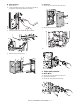
B. Lift motor C. Clutch 1) Remove the drive unit. 1) Remove the paper feed unit. (Refer to "3. Each unit removal.") 2) Remove the E-ring, and remove the parts. 2) Remove the screw, and remove the cover. 3) Remove the screw, and remove the cover. 3) Remove the E-ring, and remove the parts. 4) Disconnect the connector, and remove the screw. 5) Remove the frame. 4) 5) Remove the screw, and remove the lift motor. Remove the ring, and remove the pulley.
6) Remove the connector, and the E-ring, and remove the paper feed, transport clutch, respectively. E. Torque limiter 1) Remove the paper feed unit. 2) Remove the cover. 3) Remove the E-ring and the screw, and remove the parts. 4) Lift the shaft, and remove the torque limiter. D. Paper feed solenoid 1) Remove the paper feed unit. 2) Remove the cover. 3) Remove the screw, and remove the unit. 4) Disconnect the connector. 5) Remove the screw, and remove the solenoid.
F. Transport roller 1) Remove the paper feed unit. 2) Remove the cover. 3) Remove the spring, and remove the screw. 4) Remove the plate cover, and remove the lever. 5) Remove the clutch. 6) Remove the screw and the E-ring, and remove the parts. 7) Remove the transport roller.
[7] MAINTENANCE MX-LCX2 Service Manual 1. Maintenance system table ✕ : Checking (clean, replace or adjust as required) No.
MX-LCX2 [8] ADJUSTMENTS Service Manual Each adjustment item in the adjustment item list is indicated with its JOB number. Perform the adjustment procedures in the sequence of Job numbers from the smallest to the greatest. However, there is no need to perform all the adjustment items. Perform only the necessary adjustments according to the need. Unnecessary adjustments can be omitted. Even in this case, however, the sequence from the smallest to the greatest JOB number must be observed.
<> Item A B Display item and details BK-MAG MFT C D E F G H I J CS1 CS2 CS3 CS4 LCC ADU MULTI COUNT PAPER K DUPLEX MFT CS1 CS2 CS3 CS4 LCC YES NO Descriptions Main scanning print magnification BK Print off-center adjustment value (manual) Print off-center adjustment value (cassette 1) Print off-center adjustment value (cassette 2) Print off-center adjustment value (cassette 3) Print off-center adjustment value (cassette 4) Print off-center adjustment value (LCC) Print off-center
<> Item Button A B C D E F G H I J K L M N O P Q R S T U V W X Y ENGIN Item to be displayed TRAY1(S) TRAY2(S) TRAY3 PLAIN PAPER (S) TRAY3 PLAIN PAPER (L) TRAY3 HEAVY PAPER1 (S) TRAY3 HEAVY PAPER1 (L) TRAY4 PLAIN PAPER (S) TRAY4 PLAIN PAPER (L) TRAY4 HEAVY PAPER1 (S) TRAY4 HEAVY PAPER1 (L) MANUAL PLAIN PAPER (S) MANUAL PLAIN PAPER (L) MANUAL HEAVY PAPER1 (S) MANUAL HEAVY PAPER1 (L) MANUAL OHP1 MANUAL ENV ADU PLAIN PAPER (S) ADU PLAIN PAPER (L) ADU HEAVY PAPER1 (S
2-B Print lead edge adjustment 1) Execute SIM.50-5 by the key operation of the machine. Then, the displays shown on the right side appear. 2) Press the [↓] key on the touch panel to select “E:PAPER”. 3) Then, enter the adjustment value 6 with the [10] key, and press the [OK] button. (Adjustment value 6: LCC) 4) 5) When the [EXECUTE] button is pressed, the [EXECUTE] button is highlighted, and printing for adjustment pattern image is started with the currently set value.
Item Display items and details Descriptions Setup range Default Writing A DEN-C Print lead edge adjustment 1 to 99 30 Yes B DEN-B Sub scanning direction print area adjustment 1 to 99 20 Yes C FRONT/REAR FRONT/REAR void amount adjustment 1 to 99 20 Yes D MULTI COUNT Number of printed sheets 1 to 999 1 No 2 (CS1) No 1 (NO) No E PAPER F DUPLEX MFT CS1 CS2 CS3 CS4 LCC YES NO Cassette selection Double-sided print selection Manual 1 Cassette 1 Casset
MX-LCX2 [9] SIMULATION Service Manual 1. List Code Main Function (purpose) Sub 2 4 3 15 Purpose Used to check the operations of the sensors and detectors in the large capacity tray (LCC) and the control circuit. Used to check the operations of the loads in the large capacity tray (LCC) and the control circuit. Operation test/Check Operation test/Check 5 Used to check the operations of the clutch (LTRC) in the LCC and the monitor.
4-5 15 Operation test/Check Purpose Function (Purpose) Used to check the operations of the clutch (LTRC) in the LCC and the monitor. Large capacity tray (LCC) Section 15-Clear/cancel (Trouble etc.) Purpose Function (Purpose) Used to cancel the self-diag "U6-09 F3-12, F3-22(largecapacity paper feed tray, paper feed tray 1, 2)" trouble. Operation/Procedure 1) Press LTRC key to check the sync signal.
[10] SELF DIAG MESSAGE AND TROUBLE CODE MX-LCX2 1. Self diag Service Manual Monitors the machine conditions. Detects/analyzes the content. A. General When a trouble occurs in the machine or when the life of a consumable part is nearly expired or when the life is expired, the machine detects and displays it on the display section or notifies to the user or the serviceman by voice messages. This allows the user and the serviceman to take the suitable action.
2. Trouble code list No. 1 2 3 4 5 MAIN CODE U6 SUB CODE 09 20 21 22 51 Title (Content) Lift motor trouble Communication trouble Transport motor trouble 24V trouble LCC incompatibility trouble Section LCC LCC LCC LCC LCC 3. Trouble code details U6-09 LCC lift motor trouble Trouble content Section Case 1 Cause Check and Remedy • The encoder input value is not changed in 0.2sec (1st time)/0.5sec (2nd time and later) after rotation of the motor. • The motor is rotated for 24sec or more.
MX-LCX2 [11] ELECTRICAL SECTION Service Manual 1. Electronic/mechanical parts relationship diagram CN-B B8B-PH-K-S 1 +5V +5V 2 3 LRE 4 LDD 5 GND2 6 GND2 7 +24V (/LTLS) 8 CN-E B14B-PHDSS-B +5V LCD GND2 GND2 LLM N.C. LLM(GND) N.C.
MX-2300/2700 F AC-N AC-L +24V GND1 GND2 +5V /TRC-LCC RES-LCC /DTR-LCC F /DSR-LCC /TXD-LCC /RXD-LCC MX-LCX2 Ground Heater +24V +5V Xtal 7.37MHz MX-LCX2 ELECTRICAL SECTION 11 – 2 EEPROM On-board write circuit GND2 Input buffer Input buffer Input buffer Output buffer Input buffer Output buffer LCC MAIN PWB CR CPU (H8/3687HV) LLSW - LDSW - L24VM (TD62003AP) Transistor array Sensor input circuit Upper limit monitoring circuit Upper door monitoring circuit Poly switch 1.
3. Wiring diagram CN-D B10B-PHDSS-B +24V(LDSW) +24V(LLSW) GND2 GND2 +24V(LLSW) GND2 GND2 +24V(L24VM) GND2 +24V(L24VM) LCC MAIN PWB CR CN-A B12B-PHDSS-B +24V GND1 N.C. N.C. +5V GND2 /TXD-LCC /RXD-LCC /DTR-LCC /DSR-LCC RES-LCC /TRC-LCC CN-F B14B-PHDSS-B RES_LCC /TXD_LCC GND GND +5V +5V /RES_LCC /NMI P85 P86 P87 TXD_LCC RXD_LCC N.C.
4 SMP-18V-NC 1 2 3 4 5 6 7 8 9 10 11 12 13 14 15 16 17 18 ELR-04NV 1 2 3 4 SMR-18V-N 1 2 3 4 5 6 7 8 9 10 11 12 13 14 15 16 17 18 3 PHR-3 1 2 3 PHR-3 1 2 3 SMP-03V-NC 1 2 3 SMP-02V-NC 1 2 SMR-03V-N 1 2 3 SMP-03V-NC 1 2 3 ELP-03V 1 2 3 GND2 LUD +5V ELR-03V 1 2 3 LCC paper feed clutch 1 2 3 LCD GND2 +5V 1 LLM(GND) 2 LLM PHR-5 1 +24V 2 GND1 3 /LPFM-EN 4 LPFM-T 5 /LPFM-CLK ELP-02V 1 2 LUD Tray upper limit sensor LPFC +5VR GND2 /LPFD 179228-3 1 +5V 2 /LTOD 3 GND2 SMR-03V-N 1 2 3 Paper-on
LEAD-FREE SOLDER The PWB’s of this model employs lead-free solder. The “LF” marks indicated on the PWB’s and the Service Manual mean “Lead-Free” solder. The alphabet following the LF mark shows the kind of lead-free solder. Example: Lead-Free 5mm Solder composition code (Refer to the table at the right.
* Applicable to battery-operated equipment * Applicable to battery-operated equipment
SHARP CORPORATION Digital Document System Group CS Promotion Center Yamatokoriyama, Nara 639-1186, Japan 2006 June Printed in Japan