INSTRUCTION MANUAL - /'
Note for Users in U K IMPORTANT The wires in the mains lead of this apparatus are coloured in accordance with the following code: BLUE: BROWN: Neutral Live As the colours of the wires in the mains lead of this apparatus may not correspond with the coloured markings identifying the terminals in your plug, proceed as follows: * The wire which is coloured BLUE must be connected to the terminal which is marked with the letter N or coloured BLACK.
INSTRUCTION Thank you for purchasing the SHARP Floppy Disk MZ-80SFD. It is a peripheral unit for use with the SHARP Personal Computer which can operate a maximum of 4 drives. We believe that it will be very useful as an external memory unit because of its large capacity and high speed access. Read this instruction manual carefully before using the Floppy Disk so you can use it correctly. • • • • • • • • Page Precautions .............................................. 1 Physical Characteristics ............
3 1 Precautions • Terminal resistor Which drive must or must not be fitted with a terminal resistor is dependent on the combination or number of drives to be used. For prevention of troubles, every drive leaves our plant with any terminal resistor not attached. When mounting a terminal resistor, read the directions given later carefully and attach the resistor to a right drive. I mproper attachment could cause damages to connected drives.
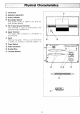
Physical Characteristics CD ® Front Door Diskette Loading Slot @ Action Indicator @ Drive Select Switch This switch serves to identify the drive by drive number setting. @ FG (Frame Ground) Terminal This terminal is used to interconnect two drives through a braided wire. @ Signal Terminal The signal cable connector is connected to this terminal. c=J) Panel Remove the panel. Then you will find there a socket to connect a terminal resistor to.
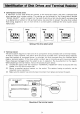
Of Disk Drives and Terminal R••lstor • Identification of disk drives A maximum of four disk drives can connect to the computer system, and every connected disk drive requires drive number setting. This setting can be achieved by the 4-gang switch labelled "DR IVE SE LECT" which is present on the back of each drive. Set only the switch corresponding to a desired drive number to ON as shown below.
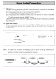
(1) Signal cable The signal cable to interconnect individual drives and the one to interconnect a drive and the interface card are different in length. (a) Interconnection of drives (or their terminals "IN" and "OUT") For this purpose use signal cable MZ-80FCK (option). (b) Interconnection of a drive and the interface card (or the terminal "IN" of the drive and the terminal of the card) For this purpose use signal cable MZ-80FC (option).
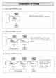
(1) When a single MZ-80SFD is used: • Set the MZ-80SFD as drive 1. Mount the terminal resistor on this drive. Q) () -t Q) C IN c:::::::J 0 U T (Drive 1) (2) When two MZ-80SFDs are used: Set these MZ-80SFDs as drives 1 and 2. Mount the terminal resistor on drive 1. • Never mount any terminal resistor on drive 2. Q) () -t ~ c (Drive 1) (Drive 2) (3) When three MZ-80SFDs are used: Q) () co 1: ~ c (Drive 3) (Drive 2) (Drive 1) Any term inal resistor must not be mounted.
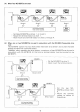
(4) When four MZ-80SFDs are used: (Drive 3) (Drive 4) (Drive 1) (Drive 2) Any term inal resistor must not be mounted. • Set these MZ-80SFDs as drives 1,2, 3, and 4. Mount the terminal resistor on drive 1. Never mount any terminal resistor on drives 2 through 4. (5) When one or two MZ-80SFDs are used in conjunction with the MZ-80FB floppy-disk drive unit: The MZ-80FB (option) has two drives which have been set as drives 1 and 2; and it has been already provided with a terminal resistor.
(6) When one or two MZ-80SFDs are used in conjunction with the MZ-80FBK floppy-disk drive unit: The MZ-80FBK (option) has two drives which have been set as drives 3 and 4; and it has not been fitted with any terminal resistor. Therefore, when upgrading the drive system, a maximum of two MZ-80SFDs can be used in conjunction with the MZ-80FBK. At this time the MZ-80SFD must be fitted with a terminal resistor. MZ-BOFBK t~~~~ Set the MZ-80SFD as drive 1 or 2. Mount the terminal resistor on the MZ-80SFD.
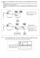
r--133.3mm rD -----I Write-protection /notch E E Center hole 1 Diskette This unit uses a 5.25" mini-disk that records on both sides as the recording medium. Its external appearance is as shown on the left. It's called a diskette and is a magnetic sheet covered by a jacket. M M - Index hole M l 0 Head window 2 Inserting a Diskette 1. Put a finger on the bottom of the front door and lightly put this door toward you to open it. 2.
Do not touch, soil or scratch the recording surface (Head Window) of the diskette with your finger. This may cause improper operation or result in no operation. Do not bend or fold the diskette or it will become unusable. Do not bring magnetic things near the diskette or the contents of the diskette will be destroyed. In addition, it's dangerous to bring a diskette near machines (motors, etc.) that generate a magnetic field.
SpeCifications Drive-to-drive connection: Recording medium: Recording: Number of tracks: Sector: Formatted capacity: Power supply: Power Consumption: Operating conditions: External dimensions: Weight: Daisy-chain system (a maximum of four drives) 5.
SHARP CORPORATION - - - - - - - - Code: MZ8XM02E TINSE0040PAZZ 811120-0500-K Printed in Japan MZ-80SFD E1