Notice for Users in the USA FCC Statement WARNING - FCC Regulations state that any unauthorized changes or modifications to this equipment not expressly approved by the manufacturer could void the user’s authority to operate this equipment. Note: This equipment has been tested and found to comply with the limits for a Class B digital device pursuant to Part 15 of the FCC Rules. These limits are designed to provide reasonable protection against harmful interference in a residential installation.
About the Modem This equipment complies with Part 68 of FCC rules. On the bottom of this equipment is a label that contains, among other information, the FCC registration number and ringer equivalence number (REN) for this equipment. If requested, this information must be provided to the telephone company. The modem jack of this equipment complies with Sub-part F of Part 68 of FCC rules. The REN is used to determine the quantity of devices which may be connected to the telephone line.
The Telephone Consumer Protection Act of 1991 makes it unlawful for any person to use a computer or other electronic device, including fax machines, to send any message unless such message clearly contains in a margin at the top or bottom of each transmitted page or on the first page of the transmission, the date and time it is sent and an identification of the business or other entity, or other individual sending the message and the telephone number of the sending machine or such business, other entity, or
Notice for Users in Europe This equipment complies with the requirements of Directives 89/336/EEC and 73/23/EEC as amended by 93/68/EEC. Dieses Gerät entspricht den Anforderungen der EG-Richtlinien 89/336/EWG und 73/23/EWG mit Änderung 93/68/EWG. Ce matériel répond aux exigences contenues dans les directives 89/336/CEE et 73/23/CEE modifiées par la directive 93/68/CEE. Dit apparaat voldoet aan de eisen van de richtlijnen 89/336/EEG en 73/23/EEG, gewijzigd door 93/68/EEG.
CAUTION: TO PREVENT ELECTRICAL SHOCK, DISCONNECT THE AC CORD AND THE BATTERY BEFORE SERVICING. CAUTION: FOR A COMPLETE ELECTRICAL DISCONNECTION, PULL OUT THE MAIN PLUG AND THE BATTERY. VORSICHT: UM DIE STROMZUFUHR VOLLSTÄNDIG ZU UNTERBRECHEN, DEN NETZSTECKER HERAUSZIEHEN UND DIE BATTERIE ÈNTFERNEN. ATTENTION: POUR UN ARRET TOTAL DU SYSTEME, DECONNECTEZ LA PRISE DE COURANT SECTEUR ET LA BATTERIE. VARNING: FÖR TOTAL ELEKTRISK URKOPPLING, KOPPLA UR KONTAKTEN OCH TA UR BATTERIET.
Safety Precautions General • • Follow all cautions and instructions which may be marked on the computer. Except as described elsewhere in this manual, refer all servicing to qualified personnel.
• • • Do not drop the computer nor hit it with other equipment. Do not scratch the surface of the LCD screen. Turn off the computer and disconnect the AC power cord before cleaning. Battery Pack Precautions Handling • • • • • • • Never put the battery pack in a fire, as it could explode and cause injury. Do not attempt to open or alter the battery pack. Do not place the battery where it might get hotter than 60°C (140°F).
Modem Precautions • • • • • • viii Never install telephone wiring during a lightning storm. Never install telephone jacks in wet locations unless the jack is specifically designed for wet locations. Never touch uninsulated telephone wires or terminals unless the telephone line has been disconnected at the network interface. Use caution when installing or modifying telephone lines. Avoid using the telephone during a lightning storm. There may be a remote risk of electric shock from lightning.
About This Manual Notice Information in this manual is subject to change without notice and does not represent a commitment on the part of SHARP Corporation. SHARP Corporation shall not be liable for technical or editorial errors or omissions contained herein; nor for incidental or consequential damages resulting from the furnishing, performance, or use of this material. SHARP strongly recommends that separate permanent written records be kept of all important data.
Recording Important Information For future reference, please record the following information in the spaces provided below. Model Number: Serial Number: Date of purchase: Dealer’s Name: Place of purchase: Password: The serial number is printed on a sticker located on the bottom of the computer.
Manual Conventions This manual uses a set of style conventions described below. Notes and Cautions are italicized with icons: A note icon informs you of a special technique or information that may help you perform a task or better understand a process. A caution icon alerts you to something that may cause problems or damage to hardware, software or data. Key Labels on the Keyboard, when referred to in the instructions, are shown in boldface: Press Enter to continue.
Table of Contents Notice for Users in the USA .......................................................................................i Notice for Users in Europe .......................................................................................iv Safety Precautions.....................................................................................................vi About This Manual ...................................................................................................
Connecting Peripherals 4-1 Using Peripheral Devices ....................................................................................... 4-1 Connecting Peripherals Overview.......................................................................... 4-2 Using PC Cards ...................................................................................................... 4-3 Connecting an External Monitor ............................................................................ 4-6 Connecting Headphones.
Appendices Appendix 1: Troubleshooting ................................................................................A-1 Appendix 2: Care & Maintenance .........................................................................A-8 Appendix 3: Specifications ..................................................................................A-10 Index Index ................................................................................................................
Overview of Computer In the following diagram, the labels in italics refer to the chapter and page number in this manual where you can find more information. The actual appearance of your computer may be slightly different depending on the model.
Right Side View PC card slot See 4-3 PC card eject button See 4-4 Drive bay with CD-ROM drive installed See 2-15 Drive activity indicator Manual tray eject button (recessed) Eject tray button Left Side View Slot for security cable See 7-4 K Battery lock button AC adapter jack See 1-1 xvi
Rear View Modem jack See 5-4 (may not be available in some countries) Monitor port USB port See 4-6 See 4-10 Parallel/FDD port See 4-11 Infrared port Headphone jack See 4-10 See 5-1 Bottom View Memory module compartment Port replicator docking connector See 6-4 See 6-6 Drive bay lock latch Reset switch (recessed) See 2-3 Battery See 3-1, 3-5 CD-ROM drive installed in drive bay See 2-14 xvii
CHAPTER 1 1 Fast Start Your new computer is ready to use as soon as you unpack it from the box. If you’re familiar with computers, follow the instructions in this chapter to get your system up and running in just a few minutes. If this is your first computer, you should read through the entire Operation Manual before starting the system. Connecting AC Power Run your computer the first time using AC power, rather than battery power.
2. 1 3. 4. Plug the cable from the AC adapter into the AC adapter jack on the left side of the computer. Connect the power cord to the AC adapter. Plug the power cord into a suitable power outlet. The orange battery charge indicator turns on when you connect AC power. Battery charge and power indicators Power button AC adapter jack AC adapter To power outlet 5. 6. 7. 1-2 Press the power button located just above the Pause button on the keyboard.
Setting Up Windows 98 Windows 98 is pre-installed on your computer, including the special drivers and software used by built-in components such as the audio and video system, the modem, and the PC card slot. The Windows Setup program lets you enter personal data such as your name, the date and time in your location, and so on. It takes just a few minutes to complete. The setup process has four steps: • Getting started This section asks for your name.
1 • • • PC Card Power Management System Turning Off Your Computer When you’re finished using your computer, turn it off with the following steps: 1. 2. 3. Click the Start button in the taskbar and click on Shut Down from the Start menu. In the Shut Down Windows dialog box, check the Shut down item and then click the OK button. The power indicator turns off. Close the cover to keep the screen and keyboard clean and protected. You can shut down the computer with the power button using the steps below: 1.
CHAPTER 2 Basic Operations 2 This chapter describes some of the basic operations of your computer such as using the keyboard, adjusting the display, and so on. Powering the Computer You can operate your computer by using the AC adapter to connect to a suitable power outlet. You can also power the computer by the internal Lithium-Ion battery. Whenever you use the AC adapter to power the computer, the internal battery automatically begins recharging.
Power and Battery Indicators 2 For proper operations it is important to understand the operation of the power and battery indicators located beside the right-side hinge of the upper cover.
Resetting the System You may need to reset the system after adding hardware or software so that your computer recognizes newly installed devices or software. When the message appears after the installation, click OK, Yes, etc., to restart Windows 98. You can also restart Windows 98 from the Start menu. Select Shut Down, then Restart. Warm Boot (Software Reset) If the system is locked up because of a software problem, you can reset or reboot the system by pressing the Ctrl+Alt+Del keys simultaneously.
Using the Keyboard 2 The built-in keyboard includes all the functions that you find on a full-sized keyboard. In addition, the keyboard has built-in hot keys that you can use to control some of the functions of the computer. The illustration below shows the location of some important keys on your keyboard.
Windows Keys There are two different Windows keys as shown below. The keyboard repeats the Windows Start key on either side of the Space bar. Windows Start Key. This key opens the Windows Start menu on the taskbar. In combination with other keys it provides short cuts to some Windows functions. See Windows help for more information. Windows Pull-down Menu key. When an item is selected and this key is pressed, it pulls down a menu if one is available. It is similar to the right click of a mouse or glide pad.
2 Fn + Fn + Fn + Fn + Fn + Returns the Sys Request keystroke Insert NumLk Returns the Num Lock keystroke – activates the embedded numeric keypad Returns the Scroll Lock keystroke Delete ScrLk Returns the Home keystroke Pg Up Home Returns the End keystroke Pg Dn End Pop-Up Power Management Information Box When you hold down the Fn key and press the F2 function key, a pop-up information box appears for about five seconds in the top left corner of the display.
Using the Glide Pad Your computer has a built-in pointing device called a glide pad. The glide pad consists of the glide pad surface, a left button and a right button. Glide pad surface 2 Left button Right button Using the Glide Pad When you slide your finger across the glide pad surface, the pointer on the screen moves in the same direction as your fingertip. Clicking and double-clicking To click or double-click objects, you can use the left button, just as you do when using a mouse.
Changing the Glide Pad Configuration 2 You can change the way the glide pad operates in the Mouse Properties window. From Windows Start menu, select Settings - Control Panel and double-click Mouse to open up the Mouse Properties window. Click on any of the tabs; Buttons, Pointers or Motion. Use the checkboxes, drop down menus, and so on, to configure the glide pad so that it operates to your satisfaction.
Adjusting the Display The most important adjustment you can make to the display is to set it to the best viewing angle. The display contrast decreases if you look at it from a wide angle above or below, or from side to side. 2 Changing the Brightness Change the screen brightness by using the Fn+F6 and Fn+F7 hot keys.
Changing the Display Properties 2 The Windows Display Properties window lets you make many different kinds of changes to the appearance of the screen under Windows. Place the screen pointer on any empty area of the Windows desktop and click the right glide pad button to pull down a menu. Click on Properties to open the Display Properties window.
Controlling Audio Your computer is installed with a built-in speaker and a built-in microphone. You can use Windows Entertainment Accessories to play CDs, record messages and sound, play computer games with sound tracks, and so on. 2 Microphone Speaker You can control the audio volume by using the audio hot keys Fn+F8 and Fn+F9.
Using the Drives 2 Your computer has three different drives; the internal hard disk drive, the CD-ROM drive module, and the floppy disk drive module. The CD-ROM and floppy disk drive modules can be installed in the drive bay on the right side of the computer.
CD-ROM drive The CD-ROM drive lets you read information from CDs. Your computer identifies the CD-ROM as drive R: and it is a read-only drive. You cannot write information to CD-ROMs. Many software applications and reference works are shipped on CDs because they store over 600 MB of data. Using Windows Entertainment Accessories, you can also use the CD-ROM drive to play CD-Audio disks and Video CD disks.
Installing a Drive in the Drive Bay 2 The drive bay on the right side of your computer can be installed with a CD-ROM drive or a floppy disk drive. Change the drives in the bay by following the steps below. 1. 2. 3. Remove any floppy disks or CD-ROMs from the drive that is currently installed in the drive bay. Shut down your computer and disconnect the AC adapter if it’s connected. Close the upper cover of the computer. Turn the computer over and locate the drive bay lock latch.
Using the CD-ROM Drive If the CD-ROM drive is installed in the drive bay, use it as follows. 1. Locate and identify the three features on the front of the CD-ROM drive; the eject tray button, the recessed mechanical eject button, and the drive activity indicator. Manual tray eject button (recessed) Activity indicator 2. 3. 4. 5. 6. Eject tray button Press the eject tray button to eject the tray for the CD-ROM disk.
Using the Floppy Disk Drive Externally 2 To remove the floppy disk drive from the optional floppy disk drive box (CE-FC01), press the lock latch on the top edge of the cover and pull the floppy disk drive out of the box. Press lock latch back Pull drive out of box To use the floppy disk drive as an external drive, follow the steps below: 1. 2. 3. 4. 2-16 Install the floppy disk drive into the floppy disk drive box. Simply slide the drive in until it clicks into place. Shut down your computer.
CHAPTER 3 Battery and Power Management This chapter explains how to charge your computer’s internal battery and keep it in good condition. It also explains how you can use the power management features to maximize battery life while operating under battery power. 3 Battery Pack The removable battery pack is installed in the base of the computer. If you have an optional spare battery pack (Model CE-BL08) you can double the operating time of your computer when there is no AC power available.
Battery Charging The battery pack begins charging anytime your computer is connected to AC power using the AC adapter. If the battery pack is fully discharged and your computer is turned off or in standby mode, the battery pack fully recharges in about 2 hours. If the battery pack is fully discharged and your computer is turned on, the battery pack fully recharges in about 4 hours. 3 Your computer monitors the internal temperature of the unit.
Battery Low Warnings The battery low warnings are set using the Windows Power Management Properties application. See later in this chapter for a full discussion of this topic. The Power Management Properties application lets you set a Low Battery Alarm and a Critical Battery Alarm. The alarms are triggered when battery charge decreases to a user-defined percentage set in the Power Management Properties application.
Battery Conditioning If you feel that the battery charge meter in Windows is becoming inaccurate, we recommend that you ”condition” the battery using the following steps below. The following procedure helps to keep your battery in good condition so we suggest that you carry out the procedure each time you complete about 30 cycles of charging and discharging the battery pack. 3 1. 2. 3. 4. 5. 6. 7. 8. 9. 3-4 Connect your computer to a power outlet with the AC adapter.
Changing a Battery Pack The procedure to remove and install a battery pack is as follows: 1. 2. 3. Turn off the computer, close the upper cover and turn the computer over and lay on a soft surface. On the left side of the computer, locate the battery lock button. On the base of the computer, locate the pressure point embossed on the base of the battery pack for pushing it out of the battery compartment. 3 Raised ribs to push battery pack Battery pack 4. 5. 6. 7.
Programmable Power Management Your computer supports ACPI (Advanced Configuration and Power management Interface) which is a powerful feature of the Windows 98 operating system. Therefore you can select and control all the power management of your computer through the Windows Power Management Properties application in Windows Control Panel. If you ever run your computer using an operating system that does not have ACPI, you can use the power management features that are built into the system hardware.
Setting Power Schemes The Power Management Properties window opens on the Power Schemes tab. You can use this window to create and name different Power Schemes. For each Power Scheme, you can use the drop down menus to set the timeouts for System standby, for Turn off monitor, and for Turn off hard disks. A timeout defines the length of time a component remains inactive before it is automatically turned off.
Resuming from Standby/suspend-to-RAM Mode Your computer will resume from a standby/suspend-to-RAM mode under the following conditions: • • • 3 The power button is pressed Any key on the keyboard is pressed An incoming call to the built-in fax/modem, or a PC card modem in the PC card slot, is received Setting Alarms Click on the Alarms tab of the Power Management Properties window to display the alarm options.
Use the check boxes to turn the Low battery alarm and the Critical battery alarm on or off. Use the slider bars to set the percentage of battery charge remaining required to trigger the alarms. Click on the Alarm Action button to define the actions that are generated by the alarms. We recommend that save your work and shut down the system when the battery charge is no less than 5%. Set the alarms for your own convenience so that you can shut down your system in an orderly manner.
Power Management Hot-keys In addition to the programmable power management, you can use the power management hot-keys to directly control the power consumption of your computer with just a keystroke.
CHAPTER 4 Connecting Peripherals This chapter describes how to connect your computer to peripheral devices using the input/output ports on the rear edge of the unit. To ensure correct operation follow the instructions given in this chapter, and always read the instructions given with the peripheral device as well. 4 Using Peripheral Devices You can connect and use the peripheral devices shown in the overview on the following page.
Connecting Peripherals Overview The illustration below shows many of the peripheral devices that can be connected to your computer. 4 PC card slot Modem jack Parallel (printer)/FDD port External monitor port Infrared port USB (Universal Serial Bus) port Headphone jack For information on using the modem telephone socket and the infrared port, see the following chapter Chapter5 Communication Functions.
Using PC Cards Your computer has a PC card slot on the right side. The PC card slot accepts type-1 and type-II PC cards. It supports the 32-bit Cardbus standard. You can use PC cards to add many different features to your computer such as a network adapter, a SCSI host adapter, and so on. If you use a PC card to add a feature that already exists on your computer, such as a fax/modem, this may cause problems as the devices compete for limited resources.
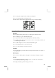
Configuring a PC Card 1. 2. 3. 4 4. The Windows operating system immediately detects the insertion of the card. If Windows recognizes the card it automatically loads any drivers required by the card, and allocates any resources that are required by the card. Windows usually displays a New Hardware Found dialog box that tells you that the card has been successfully configured. The next time you use the card, Windows configures it automatically without interruption.
5. Push the eject button straight into the computer chassis so that it forces the PC card out of the PC card slot. Push eject button straight into the chassis to force the card from the slot 6. 7. 4 Pull the card out of the slot. Pull the eject card button out of the computer chassis and fold it back against the side of the computer for safekeeping.
Connecting an External Monitor You can connect an external monitor to your computer and then display the video output to either the built-in screen, the external monitor, or a simultaneous display to both the monitor and the screen. You can even create dual independent displays so that, for example, you can run one application on the built-in screen, and run a different application on the external monitor. Connecting the monitor 1. 2.
4 4. 5. 6. Use the check boxes to turn on or off the display to the built-in screen (called LCD in this window) and the external monitor (called CRT for Cathode Ray Tube in this window). Use the slider bars to adjust the resolution and the refresh rate of the display on the external monitor. Click on Apply and verify that the display is the way you want it. Click on OK to exit the NeoMagic MagicMedia Properties window.
When you connect an external monitor and turn on the computer, the system defaults to a simultaneous display on the built-in screen. Press Fn+F5 one time Press Fn+F5 two times Press Fn+F5 three times Video display to built-in screen only Video display to external monitor only Video display to both built-in screen and external monitor Don’t try to use the display switching hot-keys while your computer is booting. It might cause the system to malfunction.
4 9. Click on the monitor marked with a number 2. Windows asks if you want to enable the monitor as an extension of your Windows desktop. Click the Yes button. 10. Use the glide pad to drag monitor 2 around monitor 1 so that it is in the same location as the real external monitor is in relation to the built-in screen. The location of the monitors determines on which edge of the built-in screen the screen pointer transits from the screen to the external monitor.
Connecting Headphones You can connect headphones to your computer so that you can listen to audio in private. When you plug headphones into the headphone jack, the built-in speaker in the computer cabinet is automatically turned off. Headphone jack You can adjust the volume by clicking on the loudspeaker icon on the right side of the taskbar, or by pressing the audio volume control hot keys.
Connecting a Printer Most printers connect through the parallel/FDD port on the rear edge of your computer. Parallel/FDD port Installing a Printer Driver After you have connected the printer to your computer through the parallel/FDD port, install a printer driver following the steps below: 1. 2. 3. 4. 5. 6. 7. 4 From the Start menu, select Settings - Printers. Double-click the Add Printer icon. The Add Printer Wizard appears. Click Next. Confirm Local printer is selected and click Next.
CHAPTER 5 Communication Functions Your computer has two important features that let you establish communications with other computers and devices. The infrared port lets you establish wireless communication with other infrared devices that are at close range. The built-in modem lets you connect to the telephone system so that you can communicate with the whole world through the internet, e-mail, etc,. Infrared Communication 5 The infrared port is located on the rear edge of your computer.
As a default, the infrared port is turned off. When the infrared port is turned on, it continually emits infrared signals to try and find a receiver. We suggest that you only turn on the infrared port when you want to use it. During infrared communications: • • • • • 1. 2. 3. 5 4. 5.
File Transfers 1. 2. 3. 4. To send a file from your computer to another Windows 98 computer, use Windows Explorer to browse to the files you want to transfer. Right click the file and select Send To from the drop down menu Click on Infrared Recipient in the Send To menu. Any files that you send are stored in the folder My Received Files on the C: drive of the target computer. Files sent from the target computer to your computer are stored in the same location on your computer.
Built-in Modem(may not available in some countries) • • The built-in modem may not be available in some countries. You cannot use the built-in modem in MS-DOS mode. You can use the built-in modem for data transfer, fax communication, and voice communication. You can also use it to establish a dial-up connection to the internet through an Internet Service Provider. • • 5 • The built-in modem on your computer is designed for regular analog telephone lines.
Connect to the telephone line directly. Do not use a distributor or allotter. Configuring the Modem You may have already configured your modem during Windows 98 Personal Setup. Otherwise, make the necessary adjustments as shown below. Telephony Configuration 1. 2. 3. 4. From the Start menu, select Settings - Control Panel. Double-click the Telephony icon. In the Dialing Properties window, type in the details about your location and dialing properties.
Hyper Terminal and Phone Dialer You can find these applications by opening the Start menu and selecting Programs, then Accessories, and then Communications. HyperTerminal lets you connect to other computer terminals, for example, Bulletin Boards. Phone Dialer lets you store and dial numbers for quick access. You can also use the LapLink program supplied with your computer to establish modem communications. See the LapLink online help for more information.
CHAPTER 6 Changing or Adding Options This chapter describes how you can change or add two important optional items to your computer; a port replicator, and a memory card. It also explains how to use the Recovery CD to repair a corrupted hard disk drive. Using the Recovery CD If your hard disk drive ever gets corrupted, for example by a computer virus, you can use the recovery CD to return the state of your hard disk to the way it was when your computer shipped from the factory.
3. 4. 5. 6. 7. 8. 9. 10. 11. 12. 13. 6 14. 6-2 In the setup utility, open the Boot page and make the CD-ROM the first boot location. See Boot Page in Chapter 8 for more information. Insert the recovery CD into the CD-ROM. Exit the setup utility saving changes. When your computer restarts it boots the recovery program from the recovery CD. The opening screen explains the recovery procedure and asks if you want to continue. Press Enter to continue, press Esc to cancel.
Adding a Memory Module Your computer comes complete with 64 MB of main memory. This is plenty of memory for most applications. However, if you want to enjoy the increased performance that extra memory can bring, you can easily add a memory module to your system using the spare memory compartment in the base of your computer. The memory compartment can be installed with an industry-standard SODIMM (Small Outline Dual In-line Memory Module).
Memory module Edge connector on module Edge connector slot 6. 7. 8. 9. 6 6-4 After the module is inserted into the slot, press it down flat into the compartment so that the spring latches inside the compartment grip the edges of the memory module and hold it in place. If you are removing an old module, press these same spring latches apart so that the memory module pops out of the compartment and then pull the edge connector of the module free from the edge connector slot.
Using the Optional Port Replicator (may not be available in some countries) The optional port replicator (model CE-DS02) provides a convenient “parking place” for your computer on your desktop or working area. It duplicates the ports on the rear edge of your computer and adds extra ports as well. You can leave peripheral devices permanently connected to the port replicator. When you dock your computer to the replicator, all the devices are instantly available.
Port Replicator Ports The port replicator ports are all located on the back side. PS/2 Keyboard USB Telephone (may not be available in some countries) PS/2 Mouse Parallel Microphone Line-out Infrared RS-232C Serial Monitor Line-in AC Adapter Docking and Undocking 6 Your computer has a connector in the base of the unit that automatically engages with the docking connector on the port replicator. The connector on the base of the computer is protected by a spring-loaded cover.
Before docking your computer to the port replicator, either turn off the computer or suspend the computer by pressing the hot keys Fn+F12. After the computer is shut down or suspended, install the computer in the port replicator. The guide pins ensure that the computer is positioned correctly. Restart your computer by pressing the power button, or resume from the suspend mode by pressing any key.
CHAPTER 7 Security Features This chapter describes how to protect your computer against unauthorized use, and theft. Passwords Setting a password will help protect against unauthorized access to your computer. When password protection is correctly set, you can leave your computer turned off or in standby/suspend-to-RAM mode. No unauthorized users can restart the system without typing in the correct password.
• Change diskette access Setting the Password in the Setup Utility 1. In the Security menu of the setup utility, select Set Supervisor Password or Set User Password and press Enter. 2. Type your password (up to eight characters), and press Enter. 3. Type the same password again, and press Enter. 4. When the confirmation message appears, press Enter. 5. Press Esc and select Exit Saving Changes. 6. Press Enter twice. The system restarts and asks the password you have set.
Password Requirements If you have enabled Password on boot in the Security page of the setup utility, the system will ask for a password when the system is started. If a user password is entered, then the user has limited access to the floppy disk drive as set by holder of the supervisor password. When the setup utility is opened, a password is required. If a user password is entered, the user does not get access to the Advanced page of the setup utility.
Using a Security Cable You can prevent theft by connecting a laptop security cable to a fixed object and locking the other end of the cable in the slot on the left side of the computer.
CHAPTER 8 Setup Utility This chapter describes how to run the setup utility to change settings on your computer. Running the Setup Utility With the setup utility, you can customize the system configuration information, such as time and date, port assignments, passwords, or power management settings. The information you have specified is saved in a special area called CMOS RAM, which the system reads every time you turn on the computer.
6. When the message Setup Confirmation appears, press Enter again. The system restarts. To turn off the computer when the setup utility is open, press the power button. Using the Setup Utility To navigate through the different menus, you can use the following keys: Use the Left and Right cursor arrow keys to choose the pages from the main menu bar across the top of the screen. Use the Up and Down cursor arrow keys to select the items on each page.
Main Page System Time Defines the system time, using the format hour:minute:second (24hour format). The Tab key moves the cursor, and the Space bar and the Plus and Minus keys change numbers. System Date Defines the system date. The Tab key moves the cursor, and the Space bar and the Plus and Minus keys change numbers. Diskette A Always set to 1.44MB,3½. You cannot change this item. Diskette B Lets you enable the floppy disk or define it as Not Installed. To use it, set this item to 1.44MB,3½".
Extended Memory Shows the size of extended memory beyond 1 MB. Advanced Page Serial port Sets the RS-232C serial port (only available on the optional Port Replicator), selecting the base I/O address. Enabled means that you can set the item yourself. Auto means that the item is automatically assigned. Disabled means that you cannot use the port. IrDA port Sets the infrared port, selecting the I/O address and IRQ channel, and the DMA channel. Enabled means that you can set the items yourself.
Security Page See Chapter 7 for detailed information on setting passwords in the Security page. Under some password settings, not all items are available to all users. Set Supervisor Password Defines the supervisor password (up to eight characters). Set User Password Defines the user password (up to eight characters). You cannot set the user password unless you have set the supervisor password. If you lose or forget your password while password protection is enabled, you lose access to your computer.
Power Page Because your computer supports ACPI (Advanced Configuration and Power management Interface), a powerful feature of the Windows 98 operating system, the power management for your system is controlled by the Windows OS and the items on this page have no function. See Chapter 3 for information on using the Windows Power Management Properties program. If you install your computer with an alternative operating system that does not have ACPI (for example Windows NT 4.
Resume on Time If you enable this item, the system can resume from suspend mode by an alarm set on the computer’s realtime clock. Resume Time If you have enabled the Resume on Time item, use this item to set the alarm time. Cooling Control Use this item to determine how the system controls the thermal management of your system. If you select Performance, the system turns on the cooling fan first when cooling is required. It only throttles the processor if further cooling is required.
Appendix 1: Troubleshooting This appendix describes how to troubleshoot problems with your computer. Common Problems Problems with your computer can be caused by something as minor as an unplugged power cord or as major as a damaged hard disk drive. The information in this troubleshooting section is designed to help you find and solve minor problems. If you still have a problem after trying all the suggested remedies in this chapter, contact your dealer.
Trouble when Starting Question: Why doesn't the power switch function? • • Make sure the AC power cable is correctly connected to a live power outlet. If the computer is operating with batteries, the batteries may be discharged. Connect the computer to a power outlet. Question: Why doesn't Windows start? • • • • Check whether the floppy disk drive unit contains a non-system disk. Remove the floppy disk from the drive, and press any key.
Trouble with the Display Question: Why is the screen blank? • • • • • • • • Press any key to see if any power management feature has turned off the screen to save power. See the power indicator to check whether the computer is powered. If you are using a battery pack, make sure it has a charge remaining Make sure the LCD screen is selected as the display by pressing Fn+F5. Check the brightness controls for your display by pressing Fn+F7. Check whether the back light is on by pressing any key.
Trouble with the Hard Disk Question: Why can't I read or write data to/from the hard disk? • • • Confirm the drive and file names are correct. Confirm the hard disk has sufficient free space. The hard disk in your computer is formatted with FAT32. You cannot read or write data formatted in other operating systems, which are not FAT 32 compatible. Applications that are not compliant with FAT32 may not work properly.
Question: Why doesn't the glide pad function correctly? • • Confirm the surface of the glide pad is completely dry and free from dirt and grease. Confirm the item PS/2 Mouse in the Main menu of the setup utility is enabled. Trouble with Peripherals Question: Why don't expansion or peripheral devices function? • • • Confirm they are correctly connected to your computer. Confirm if drivers necessary for operating ports on the devices are installed. There may not be a free IRQ (Interrupt).
• Confirm the item Serial Port is set appropriately in the Advanced menu of the setup utility. Trouble with Communication Question: Why can't I communicate through the built-in IR port? • • • • • Confirm the IR port of your computer is lined up with the IR port of the other device. These ports should be no more than 30 inches (1meter) apart without any obstacles. Confirm that IR communication is turned on in the Infrared Monitor window.
Other Troubles Question: Why is the date and/or time incorrect? • Correct the date and time using the Date/Time icon in the Windows Control Panel or the Main menu of the setup utility. Question: Why can't I produce sound? • • Check the volume control with the Fn+F9 hot keys. Click the speaker symbol on the taskbar and check the Windows volume control. Question: Why can't I use a hardware device? Make sure the hardware device is not disabled using the following procedure. 1.
Appendix 2: Care & Maintenance This appendix provides you with information on how to maintain your computer in excellent working condition. Cleaning the Computer Cabinet Apply a small amount of mild cleaning solution to a dry, lint-free cloth and wipe the cabinet with the cloth. • • Do not use alcohol, benzene, thinner or other strong chemical agents or solvents that may damage the cabinet. Never clean the computer while it is turned on.
• • • Do not travel with the computer powered on. This may result in loss of data and/or damage to the hard disk drive. Disconnect the AC adapter from the computer. Fully charge the battery pack and bring the AC adapter and the AC power cord. Avoid sudden shocks or extreme vibration.
Appendix 3: Specifications Parts CPU Secondary cache ROM RAM System Video Display Panel Video controller Keyboard Pointing device Drive Hard disk Floppy disk PC card slot Audio system I/O ports Audio Video Others Infrared Modem (may not be available in some countries) Power AC adapter Battery Battery life Battery charging time Dimensions Computer Specifications FDD box Temperature Environment A-10 Operating Humidity Specifications Mobile Pentium III Processor (frequency differs by configuration) 256
Options AC adapter................................ CE-A80V Battery Pack ............................. CE-BL08 Floppy Disk Drive Box ............ CD-FC01 Port Replicator .........................
Index AC adapter first -time use, 1-1 Audio connecting headphones, 4-10 controlling, 2-11 hot-keys, 2-11 B Battery about, 3-1 changing battery pack, 3-5 charging, 3-2 conditioning, 3-4 indicator, 2-2, 3-2 low charge warnings, 3-3 responding to low charge condition, 3-3 C Care & maintenance cleaning, A-8 traveling, A-8 CD-ROM drive about, 2-13 illustration, 2-15 installing in drive bay, 2-14 using, 2-15 D Display adjusting, 2-9 advanced settings, 2-10 changing brightness, 2-9 changing properties, 2-10 co
I Indicators power and battery, 2-2 Infrared communication about, 5-1 eastablishing a connection, 5-2 file transfers, 5-3 postioning the ports, 5-1 troubleshooting, A-6 turning off, 5-3 K keyboard using, 2-4 Keyboard embedded keypad, 2-4 Fn key combinations, 2-5 function keys, 2-4 hot-keys, 2-5 illustration, 2-4 power management hot-keys, 3-10 troubleshooting, A-4 windows keys, 2-5 M Memory module adding, 6-3 Modem about, 5-4 configuring, 5-5 connecting to telephone line, 5-4 settings, 5-6 troubleshooting
S Security locking cable, 7-4 passwords, 7-1 Setup utility about, 8-1 advanced page, 8-4 boot page, 8-7 entering and exiting, 8-1 exit page, 8-7 main page, 8-3 power page, 8-6 running, 8-1 security page, 8-5 using, 8-2 Specifications reference, A-10 Standby/suspend mode about, 3-7 generating conditions, 3-7 resuming from, 3-8 setting a resume password, 7-3 Status indicators meanings, 2-8 System adding memory, 6-3 care and maintenance, A-8 optional port replicator, 6-5 resetting, 2-3 setup utility, 8-1 spec
Your computer and its accessories come securely packaged in a cardboard shipping carton. As you unpack your computer, please be sure to check for all of the following items which should be included: • Notebook Computer • AC Adapter • AC Power Cord • Floppy Disk Drive Unit • Modem Cable (may not be available in some countries) • Windows 98 Pack • Operation Manual ∗ Carefully inspect each component to make sure nothing is missing or damaged.