PG-B10S Projection Functions Using the Menu Connections LCD PROJECTOR Basic Operation MODEL Introduction OPERATION MANUAL Screen Setup Appendix
IMPORTANT For your assistance in reporting the loss or theft of your Projector, please record the Serial Number located on the bottom of the projector and retain this information. Before recycling the packaging, please be sure that you have checked the contents of the carton thoroughly against the list of “Supplied accessories” on page 9. Model No.: PG-B10S Serial No.: This equipment complies with the requirements of Directives 89/336/EEC and 73/23/EEC as amended by 93/68/ EEC.
SPECIAL NOTE FOR USERS IN THE U.K. The mains lead of this product is fitted with a non-rewireable (moulded) plug incorporating a 5A fuse. Should the fuse need to be replaced, a BSI or ASTA approved BS 1362 fuse marked or and of the same rating as above, which is also indicated on the pin face of the plug, must be used. Always refit the fuse cover after replacing the fuse. Never use the plug without the fuse cover fitted.
The supplied CD-ROM contains operation instructions in English, German, French, Swedish, Spanish, Italian, Dutch, Portuguese, Chinese (Traditional Chinese and Simplified Chinese) and Korean. Carefully read through the operation instructions before operating the projector. Die mitgelieferte CD-ROM enthält Bedienungsanleitungen in Englisch, Deutsch, Französisch, Schwedisch, Spanisch, Italienisch, Niederländisch, Portugiesisch, Chinesisch (Traditionelles Chinesisch und einfaches Chinesisch) und Koreanisch.
Introduction Introduction Before using the projector, please read this operation manual carefully. ENGLISH There are two important reasons for prompt warranty registration of your new SHARP Projector, using the REGISTRATION CARD packed with the projector. 1. WARRANTY This is to assure that you immediately receive the full benefit of the parts, service and labor warranty applicable to your purchase. 2.
WARNING: The cooling fan in this projector continues to run for about 90 seconds after the projector enters the standby mode. During normal operation, when putting the projector into the standby mode always use the STANDBY button on the projector or on the remote control. Ensure the cooling fan has stopped before disconnecting the power cord. DURING NORMAL OPERATION, NEVER TURN THE PROJECTOR OFF BY DISCONNECTING THE POWER CORD. FAILURE TO OBSERVE THIS WILL RESULT IN PREMATURE LAMP FAILURE.
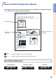
Introduction How to Read this Operation Manual • In this operation manual, the illustration and the screen display are simplified for explanation, and may differ slightly from actual display. Using the Menu Screen The menu screens allow you to adjust the image and various projector settings. The menu can be operated to achieve two functions, adjustment and setting. (For adjusting the menu items, see pages 32 and 33. For setting the menu items, see pages 34 and 35.
Contents Introduction Using the Menu How to Read this Operation Manual .................. 3 Contents ............................................................... 4 IMPORTANT SAFEGUARDS ............................... 6 How to Access the PDF Operation Manuals ..... 8 Accessories ......................................................... 9 Part Names ........................................................ 10 Menu Items ........................................................ 30 Using the Menu Screen ...
Introduction Connections Connecting the Projector to Other Devices ... 50 Before Connecting .................................................. 50 This projector can be connected to: ....................... 50 Connecting the Projector to a Computer ................. 51 Connecting to Video Equipment .............................. 52 Controlling the Projector Using a Computer ............ 54 Connecting to a Monitor ......................................... 55 Connecting the Power Cord to the Projector .......
IMPORTANT SAFEGUARDS CAUTION: Please read all of these instructions before you operate this product and save these instructions for later use. Electrical energy can perform many useful functions. This product has been engineered and manufactured to assure your personal safety. BUT IMPROPER USE CAN RESULT IN POTENTIAL ELECTRICAL SHOCK OR FIRE HAZARDS. In order not to defeat the safeguards incorporated in this product, observe the following basic rules for its installation, use and servicing. 1.
Introduction Be sure to read the following safeguards when setting up your projector. Caution concerning the lamp unit ■ Potential hazard of glass particles if lamp ruptures. In case of lamp rupture, contact your nearest Sharp Authorized Projector Dealer or Service Center for a replacement. See “Replacing the Lamp” on page 65.
How to Access the PDF Operation Manuals PDF operation manuals in several languages are included in the CD-ROM, so that you can work with the projector, even if you do not have this manual. To utilize these manuals, you need to install Adobe Acrobat Reader on your PC (Windows or Macintosh). If you have not installed Acrobat Reader yet, you can install it from the CD-ROM. To install Acrobat Reader from the CD-ROM For Windows: 1 Insert the CD-ROM in the CD-ROM drive. 2 Double click the “My Computer” icon.
Introduction Accessories Supplied accessories Remote control RRMCGA187WJSA Two R-6 batteries (“AA” size, UM/SUM-3, HP-7 or similar) Power cord* (1) (2) For U.S., Canada, etc. (6' (1.8 m)) QACCDA016WJPZ (4) (3) For Europe, except U.K. For U.K., Hong Kong and (6' (1.8 m)) Singapore QACCVA006WJPZ (6' (1.8 m)) QACCBA015WJPZ For Australia, New Zealand and Oceania (6' (1.8 m)) QACCLA005WJPZ * Use the power cord that corresponds to the wall outlet in your country. RGB cable (9'10" (3.
Part Names Numbers in refer to the main pages in this operation manual where the topic is explained. Projector (Front and Top View) ON button 18 19 Power indicator 63 20 STANDBY button 21 For putting the projector into the standby mode. Lamp indicator 63 Temperature warning indicator 63 AUTO SYNC button 40 For automatically adjusting images when connected to a computer. INPUT button For switching input mode 1, 2 or 3. For turning the power on.
Introduction About the Indicators on the Projector Power indicator Green on/Red on ... Normal Red blinks ... Abnormal (See page 63.) Lamp indicator Green on ... Normal Green blinks ... The lamp is warming up. Red on ... Change the lamp. (See page 63.) Temperature warning indicator Off ... Normal Red on ... The internal temperature is abnormally high. (See page 63.
Part Names Numbers in refer to the main pages in this operation manual where the topic is explained. Projector (Rear View) INPUT 1 terminal 51 52 Terminal for computer RGB and component signals. RGB OUTPUT terminal Terminal for connecting video equipment with an S-video terminal. 55 52 RS-232C terminal Kensington Security Standard connector INPUT 3 terminal Terminal for connecting video equipment. Terminal for connecting a monitor. Terminal for controlling the projector using a computer.
Introduction INPUT/OUTPUT Terminals and Connectable Main Equipment RS-232C terminal Connecting the computer to control the projector. (See page 54.) INPUT 1 terminal Connecting the computer. (See page 51.) Connecting video equipment with component output terminal (DVD player, DTV decoder, etc.). (See page 53.) INPUT 3 terminal Connecting video equipment without S-video output terminal. (See page 52.
Part Names Numbers in refer to the main pages in this operation manual where the topic is explained. Remote Control (Front View) STANDBY button 21 18 ON button 32 MENU button For putting the projector into the standby mode. KEYSTONE button 20 For displaying adjustment and setting screens. For entering the Keystone Correction mode. 32 UNDO button 21 FORWARD/BACK buttons Adjustment buttons (' " \ |) • For selecting menu items.
Introduction Using the Remote Control Usable Range Remote control sensor The remote control can be used to control the projector within the ranges shown in the illustration. 30° Note • The signal from the remote control can be reflected off a screen for easy operation. However, the effective distance of the signal may differ depending on the screen material.
Setup and Projection In this section, connection of the projector and the computer is explained as an example. 3 ON button 5 INPUT button 4 KEYSTONE button 3 ON button 4 Adjustment buttons ('"\ |) 4 KEYSTONE button 4 Adjustment buttons ('"\ |) 5 INPUT 1 button 4 Zoom knob 4 Focus ring 4 Lens shift lever 4 HEIGHT ADJUST button 1. Place the projector facing a wall or a screen Page 56 2.
4. Adjust the projected image 1 Bring the projected image into focus and adjust the projected image size Zoom • Adjust the projected image size using the zoom knob. zoom in Basic Operation Focus • Bring the projected image into focus using the focus ring. zoom out Page 22 Page 22 2 Adjust the projected image position and the projector angle Projection position • Adjust the projected image position using the lens shift lever. Angle • Adjust the projector angle using the HEIGHT ADJUST button.
Image Projection Turning the Projector on Connect the required external equipment to the projector before carrying out the following procedures. (See page 50.) Info • The language preset at the factory is English. If you want to change the on-screen display to another language, reset the language according to the procedure on page 48. 1 Plug the power cord into the wall outlet. Power indicator ON button • The power indicator illuminates red, and the projector enters standby mode.
Switching the INPUT Mode Select the appropriate input mode for the connected equipment. Press , or on the remote control to select the INPUT mode. INPUT 1 mode Projection "On-screen Display of INPUT Mode (Example) ➝ • When pressing on the projector, input mode switches in order of INPUT 1 INPUT 2 INPUT 3 .
Image Projection Displaying the Black Screen and Turning off the Sound Temporarily AV MUTE button Press on the remote control to temporarily display a black screen and turn off the sound. Note • Pressing again will turn the projected image and sound back on. Correcting Trapezoidal Distortion When the image is projected either from the top or from the bottom towards the screen at an angle, the image becomes distorted trapezoidally.
2 Press ', ", \ and | to adjust the Keystone Correction. Compresses upper side. • You can also adjust the Keystone Correction using the , buttons on the projector. , and Note 3 Press Compresses lower side. Projection • Press to return to the default setting. • Straight lines or the edges of images may appear jagged while adjusting the image. . • The on-screen display of the Keystone Correction mode will disappear. • You can also use on the projector.
Image Projection Adjusting the Lens Zoom knob Focus ring The image is focused and adjusted to the desired size using the focus ring or zoom knob on the projector. 1 Adjust the focus by rotating the focus ring. 2 Adjust zooming by moving the zoom knob. m in Zoo Zoo Indication of the Projection Image Size and Projection Distance For details, see “Screen Size and Projection Distance” on page 57.
Using the Adjustment Feet The height of the projector can be adjusted using the adjustment feet at the front and rear of the projector. When the screen is in a higher position than the projector, the projection image can be made higher by adjusting the projector. Press HEIGHT ADJUST button. 2 Lift the projector to adjust its height while pressing the HEIGHT ADJUST button. Projection 1 HEIGHT ADJUST button • The front adjustment foot comes out.
Variable Lens Shift Feature In addition to the zoom function and adjustment of projection angle using the adjustment foot, it is possible to move the lens up and down and left and right (360°) to adjust the projection position simply by moving the lens shift lever on the front of the projector. This is a useful function in cases such as when the screen can not be moved.
Adjusting the Projected Image Position Adjust the projected image position using the lens shift lever. Info Projection • When using the projector (during projection), be sure not to subject the projector to any impact. If the projector is subjected to impact, the projection image may deviate from the adjusted position. • When transporting or carrying the projector, attach the lens shipping block and the lens cap to the projector.
Resize Mode This function allows you to modify or customize the resize mode to enhance the input image. Depending on the input signal, you can choose “NORMAL”, “DOT BY DOT”, “BORDER” or “STRETCH” image. Switching the Resize Mode UNDO button Press . • Pressing changes the display as shown on pages 26 and 27. • To return to the standard image, press “RESIZE” is displayed on the screen.
VIDEO 480I, 480P, NTSC, PAL, SECAM 540P, 720P, 1080I 4:3 aspect ratio. Letter box, squeeze 16:9 aspect ratio NORMAL BORDER 800 × 600 600 × 450 — — STRETCH 800 × 450 • “STRETCH” is fixed when 540P, 720P or 1080I signals are entered. Output screen image Input Signal DVD / Video NORMAL BORDER STRETCH Projects a full screen image. Projects 4:3 image fully in STRETCH (the following column) image. Projects 16:9 image evenly over entire screen (top/bottom black bands).
Freeze and Enlarge Image You can instantly freeze a moving image and enlarge a specific portion of an image with the remote control. Using these functions, you can explain the image to the audience more effectively. UNDO button ', ", \, | buttons ENLARGE (Reduce/Enlarge) buttons FREEZE button Freezing a Moving Image 1 Press . Displaying an Enlarged Portion of an Image 1 Press . • Pressing or the projected image. • The projected image is frozen.
Keylock Function Use this function to lock the operation buttons on the projector. ON button Taking the Keylock off Hold down on the projector for about 3 seconds while the projector is being turned on. Hold down 3 seconds. Note • The keylock function does not affect the operation with the remote control buttons. • You cannot use the keylock function while the projector is warming up.
Menu Items The following shows the items that can be set in the projector.
“Options” menu Main menu Options Page 41 Sub menu Lamp Timer (Life) Page 41 OSD Display [ON/OFF] Page 41 Video System Page 42 Background Page 42 Auto PAL NTSC3.58 SECAM NTSC4.
Using the Menu Screen The menu screens allow you to adjust the image and various projector settings. The menu can be operated to achieve two functions, adjustment and setting. (For adjusting the menu items, see pages 32 and 33. For setting the menu items, see pages 34 and 35.) Example: “Picture” menu screen for INPUT 1 (RGB) mode Menu Selections (Adjustments) • The following procedure is the operating method in an adjustment menu.
3 Press ' or " to select the item you want to adjust. • The selected item is highlighted. Note • To display a single adjustment item, press after selecting the item. Only the selected adjustment item will be displayed. When pressing ' or ", the following item (“Red” after “Bright”) will be displayed. • Press to return to the previous screen. 4 Press \ or | to adjust the item selected. • The adjustment is stored. Using the Menu 5 Press . • The menu screen will disappear.
Using the Menu Screen Menu Selections (Settings) • The following procedure is the operating method in a setting menu. • This operation can also be performed by using the buttons on the projector. ENTER button 1 Press . • The “Picture” menu screen for the selected input mode is displayed. Note • The on-screen display shown on the right is displayed when INPUT 1 (RGB) mode is selected. 2 Press \ or | to display the other menu screens. • The menu icon for the selected menu screen is highlighted.
3 Press ' or " to select the item you want to set, and then press | to display the sub menu. • The selected item is highlighted. • When you select “Password” or “Anti. Theft” on the “Options” menu, press Note • Press or \ to return to the previous screen. • For some items, press \ or | to select the icon using “ ”. Press ' or " to select the setting of the item displayed in the sub menu. 5 Press 6 Press Using the Menu 4 Sub menu . • The item selected is set. . • The menu screen will disappear.
Picture Adjustment You can adjust the projector’s picture to your preferences using the “Picture” menu. Adjusting the Image Select the item on the “Picture” menu and adjust the image. Adjusting the menu screen Page 32 Example: “Picture” screen menu for INPUT 1 (RGB) mode CLR Temp (Adjusting the Color Temperature) Select “CLR Temp” on the “Picture” menu and the desired color temperature setting.
Gamma (Gamma Correction) Gamma is an image quality enhancement function that offers a richer image by brightening the darker portions of the image without altering the brightness of the brighter portions. When you are displaying images with frequent dark scenes, such as a film or concert, or when you are displaying images in a bright room, this feature makes the dark scenes easier to see and gives the impression of greater depth in the image.
Picture Adjustment Signal Type (Signal Type Setting) The signal type setting is preset to “Auto”; however, in rare cases a clear picture may not be displayed. In that case, select “RGB” or “Component” in accordance with the input signal. Select “Signal Type” on the “Picture” menu and set it to “Auto”, “RGB” or “Component” for INPUT 1.
Computer Image Adjustment Using the “Fine Sync” menu, you can adjust the computer image, match the computer display mode, and check the input signal. Adjusting the Computer Image When “Auto Sync” is set to OFF or when vertical stripes or flickering occur in portions of the screen even if “Auto Sync” is set to ON, adjust “Clock”, “Phase”, “H-Pos” or “V-Pos” to obtain the best computer image. Select the item on the “Fine Sync” menu and adjust the computer image.
Computer Image Adjustment Auto Sync (Auto Sync Adjust- Signal Info (Checking the ment) Input Signal) Used to automatically adjust a computer image. Select “Signal Info” on the “Fine Sync” menu to check the current input signal information. Select “Auto Sync” on the “Fine Sync” menu and set it to “ ”(ON) or “ ”(OFF).
Using the “Options” Menu You can use the “Options” menu to enhance the usage for the projector. Lamp Timer (Life) (Check- OSD Display (Setting On- ing the Lamp Life Status) screen Display) You can confirm the cumulative lamp usage time and the remaining lamp life (percentage). This function allows you to turn the on-screen messages on or off. Display the “Options” menu to check the lamp life status. Select “ ” (ON) or “ ” (OFF) in “OSD Display” on the “Options” menu.
Using the “Options” Menu Video System) Video System Background (Selecting a Startup and Background Image) The video input system mode is preset to “Auto”; however, a clear picture from the connected audio-visual equipment may not be received, depending on the video signal difference. In that case, switch the video signal. Select “Background” on the “Options” menu and the image displayed upon the projector’s startup and when no signal is being sent to the projector.
Eco Mode (Setting the Eco Auto Power Off (Auto Power Off Function) Mode) Select “ ” (Eco Mode) or “ ” (Standard Mode) in “Eco Mode” on the “Options” menu. Setting the menu screen Page 34 When no input signal is detected for more than 15 minutes, the projector will automatically enter the standby mode if set to “ ” (ON). The Auto Power Off function will be disabled if it has been set to “ ” (OFF).
Using the “Options” Menu Menu Position (Selecting Menu Color (Selecting the the Menu Screen Position) Menu Color) Select “Menu Position” on the “Options” menu and the desired position for the menu screen. Select “ ” (Opaque) or “ ” (Translucent) in “Menu Color” on the “Options” menu.
Password If you want to change the password, follow the procedure below. (Setting a Password) A password must be set to activate the “AntiTheft” function (Page 46). There is no factory preset for the password or the “Anti-Theft” settings. In this way, anyone can freely set a new password and “Anti-Theft” settings. It is therefore recommended that even if you do not want to use the “Anti-Theft” function, you at least set a password to prevent others from setting the “Anti-Theft” function.
Using the “Options” Menu Anti-Theft 3 (Setting the Anti-Theft) The anti-theft function prevents unauthorized use of the projector. You can choose to use this function or not. If you do not want to use this function, just do not enter the keycode. Once the anti-theft function is activated, users will need to enter the correct keycode each time the projector is turned on. Failure to enter the correct keycode will cause images to not be projected. The following procedures explain how to use this function.
If you want to change the keycode, follow the procedure below. If you want to clear the keycode input box, follow the procedure below. ▼Keycode input box Note Note • When “Anti-Theft” is selected, the password input box will appear. After the password has been entered, you can change the keycode. 1 2 Press any button you like on the remote control or the projector to enter the new keycode. Enter the same 4-digit keycode in “Reconfirm”.
Using the “Language” Menu Selecting the On-screen Display Language The on-screen display language of the projector can be set to English, German, Spanish, Dutch, French, Italian, Swedish, Portuguese, Chinese, Korean or Japanese. ENTER button Display the “Language” menu and select the desired language as the on-screen display. Example: “Language” menu screen for INPUT 1 (RGB) mode MENU button ', ", \, | buttons 1 Press 2 Press \ or | to select the “Language” menu icon. on the remote control.
Using the “PRJ Mode” Menu Reversing the Projected Image ENTER button You can reverse the projected image for various applications using the “PRJ Mode” menu. Display the “PRJ Mode” menu and select the desired projection mode. Example: “PRJ Mode” menu screen for INPUT 1 (RGB) mode MENU button ', ", \, | buttons Press 2 Press \ or | to select the “PRJ Mode” menu icon. Using the Menu 1 on the remote control. • The “Picture” menu will be displayed. • The “PRJ Mode” menu will be displayed.
Connecting the Projector to Other Devices Before Connecting Note • Before connecting, be sure to unplug the power cord of the projector from the AC outlet and turn off the devices to be connected. After making all connections, turn on the projector and then the other devices. When connecting a computer, be sure that it is the last device to be turned on after all the connections are made. • Be sure to read the operation manuals of the devices to be connected before making connections.
Connecting the Projector to a Computer Connecting to a Computer Using the RGB Cable 1 Connect the projector to the computer using the supplied RGB cable. • Secure the connectors by tightening the thumbscrews. 2 Supplied accessory RGB cable Computer To RGB output terminal To audio output terminal To input an audio signal, connect the projector to the computer using a ø3.5 mm stereo or mono audio cable (commercially available or available as Sharp service part QCNWGA038WJPZ). Note 1 RGB cable 2 ø3.
Connecting the Projector to Other Devices Connecting to Video Equipment Connecting to Video Equipment Using an S-video, a Composite Video or an Audio Cable VCR or other audio-visual equipment To S-video output terminal To video output terminal To audio output terminal Using an S-video, video, or audio cable, a VCR, laser disc player or other audio-visual equipment can be connected to INPUT 2, INPUT 3 and AUDIO input terminals.
Connecting to Component Video Equipment Use a 3 RCA to 15-pin D-sub cable when connecting to the INPUT 1 terminal, component video equipment such as DVD players and DTV* decoders. *DTV is the umbrella term used to describe the new digital television system in the United States. 1 Optional cable 3RCA to 15-pin D-sub cable AN-C3CP (9'10" (3.
Connecting the Projector to Other Devices Controlling the Projector Using a Computer Connecting to a Computer Using a DIN-Dsub RS-232C Adaptor and an RS-232C Serial Control Cable When the RS-232C terminal on the projector is connected to a computer with a DIN-D-sub RS-232C adaptor (sold separately) and an RS232C serial control cable (cross type, sold separately), the computer can be used to control the projector and check the status of the projector. See page 69 for details.
Connecting to a Monitor Watching Images on Both the Projector and a Monitor You can display computer images on both the projector and a separate monitor using RGB cables. 1 Supplied accessory RGB cable Computer RGB cable AN-C10BM (32'10" (10.0 m)) Optional cable Computer Connect the projector to the computer using the supplied RGB cable. To RGB input port • Secure the connectors by tightening the thumbscrews.
Setting up the Screen Position the projector perpendicular to the screen with all feet flat and level to achieve an optimal image. Note • The projector lens should be centered in the middle of the screen. If the horizontal line passing through the lens center is not perpendicular to the screen, the image will be distorted, making viewing difficult. • For an optimal image, position the screen so that it is not in direct sunlight or room light.
Screen Size and Projection Distance NORMAL Mode (4:3) Distance from the lens center to the bottom of the image [H] Diag. [ χ ] Width Height Lower [H1] Upper [H2] Distance from the lens center to the center of the image [W] 300" (762 cm) 610 cm (240”) 457 cm (180") 9.0 m (29' 6") 11.3 m (37' 1") 458.1 cm (180 23/64") 0 cm (0") ±181.1 cm(±71 19/64") 250" (635 cm) 508 cm (200") 381 cm (150") 7.5 m (24' 7") 9.4 m (30'10") 381.8 cm (150 5/16") 0 cm (0") ±150.
Setting up the Screen Projecting a Reversed Image Projection from behind the Screen ■ Place a translucent screen between the projector and the audience. ■ Reverse the image by setting “Rear” in the “PRJ Mode” menu. (See page 49.) Audience When the image is projected from behind the screen using the default setting. ▼On-screen Display Translucent screen Projection Using a Mirror ■ Place a mirror (normal flat type) in front of the lens.
Carrying the Projector How to Use the Carrying Case When carrying the projector, attach the lens cap and the lens shipping block to the lens, and place it in the supplied carrying case. 1 Open the cover of the carrying case. 2 Remove the inner padding from the carrying case, and fold it in the direction of the arrows. 3 Reinsert the inner padding into the carrying case. Info • Be sure to insert the inner padding to protect the lens and the projector.
Maintenance Cleaning the projector Cleaning the lens ■ Be sure to unplug the power cord before cleaning the projector. ■ The cabinet as well as the operation panel is made of plastic. Avoid using benzene or thinner, as these can damage the finish on the cabinet. ■ Do not use volatile agents such as insecticides on the projector. Do not attach rubber or plastic items to the projector for a long time.
Replacing the Air Filter • This projector is equipped with air filters to ensure the optimal operating condition of the projector. • The air filters should be cleaned every 100 hours of use. Clean the filters more often when the projector is used in a dusty or smoky location. • Ask your nearest Sharp Authorized Projector Dealer or Service Center to exchange the filter (PFILDA010WJZZ) when it is no longer possible to clean.
Replacing the Air Filter 4 Remove the air filter. 5 Clean the air filter. 6 Replace the air filter. 7 Replace the filter cover. • Pick the air filter up with your fingers and lift it out of the filter cover. • Clean the dust off the air filter and cover with a vacuum cleaner extension hose. • Place the air filter underneath the tabs on the filter cover. • Align the tab on the filter cover and place it while pressing the tab to close it (1).
Maintenance Indicators ■ The warning lights on the projector indicate problems inside the projector. ■ If a problem occurs, either the temperature warning indicator or the lamp indicator will illuminate red, and the projector will enter the standby mode. After the projector has entered the standby mode, follow the procedures given below.
Maintenance Indicators Info • If the temperature warning indicator illuminates, and the projector enters the standby mode, follow the possible solutions on the previous page and then wait until the projector has cooled down completely before plugging in the power cord and turning the power back on. (At least 5 minutes.
Regarding the Lamp Lamp ■ It is recommended that the lamp (sold separately) be replaced when the remaining lamp life becomes 5% or less, or when you notice a significant deterioration in the picture and color quality. The lamp life (percentage) can be checked with the on-screen display. See page 41. ■ For lamp replacement, please consult your nearest Sharp Authorized Projector Dealer or Service Center. IMPORTANT NOTE TO U.S.
Regarding the Lamp Removing and Installing the Lamp Unit Lamp unit BQC-PGB10S//1 Info • Be sure to remove the lamp unit using the handle. Be sure not to touch the glass surface of the lamp unit or the inside of the projector. • To avoid injury to yourself and damage to the lamp, be sure to carefully follow the steps below. • Do not loosen other screws except for the lamp unit cover and lamp unit. • Please refer to the installation manual included with the lamp unit.
5 Remove the lamp unit. 6 Insert the new lamp unit. 7 Handle • Loosen the securing screws from the lamp unit. Hold the lamp unit by the handle and pull it in the direction of the arrow. At this time, keep the lamp unit horizontal and do not tilt it. • Press the lamp unit firmly into the lamp unit compartment. Fasten the securing screws. Securing screws Replace the lamp unit cover. • Align the tab on the lamp unit cover (1) and place it while pressing the tab (2) to close it.
Connecting Pin Assignments INPUT 1 and OUTPUT RGB Signal Terminal: 15-pin Mini D-sub female connector RGB Input 10 5 6 1 15 11 1. 2. 3. 4. 5. 6. 7. 8. 9. 10. 11. 12. 13. 14. 15. Component Input Video input (red) Video input (green/sync on green) Video input (blue) Not connected Not connected Earth (red) Earth (green/sync on green) Earth (blue) Not connected GND Not connected Bi-directional data Horizontal sync signal: TTL level Vertical sync signal: TTL level Data clock 1. 2. 3. 4. 5. 6. 7. 8. 9. 10.
RS-232C Specifications and Command Settings PC control A computer can be used to control the projector by connecting an RS-232C serial control cable (cross type, sold separately) to the projector. (See page 54 for connection.) Communication conditions Set the serial port settings of the computer to match that of the table. Signal format: Conforms to RS-232C standard.
Computer Compatibility Chart Computer • Multiple signal support Horizontal Frequency: 15–70 kHz, Vertical Frequency: 43–85 Hz, Pixel Clock: 12–108 MHz • Compatible with sync on green signal • SXGA+, SXGA and XGA compatible in intelligent compression • Intelligent Compression and Expansion System resizing technology The following is a list of modes that conform to VESA. However, this projector supports other signals that are not VESA standards.
Troubleshooting Problem Check • Projector power cord is not plugged into the wall outlet. • Power to the external connected devices is off. • The selected input mode is wrong. • The AV MUTE function is working. • Cables incorrectly connected to rear panel of the projector. No picture and no sound • Remote control batteries have run out. or projector does not start. • External output has not been set when connecting notebook computer. • The filter cover or the lamp unit cover is not installed correctly.
Troubleshooting Problem Check Picture is green on • Change the input signal type setting. INPUT 1 COMPONENT. Picture is pink (no green) on INPUT 1 RGB. Picture is dark. • The lamp indicator is illuminating in red. Replace the lamp. Picture is too bright and • Picture adjustments are incorrectly set. whitish.
For SHARP Assistance If you encounter any problems during setup or operation of this projector, first refer to the “Troubleshooting” section on pages 71 and 72. If this operation manual does not answer your question, please contact the SHARP Service departments listed below. Benelux SHARP Electronics Benelux BV 0900-SHARPCE (0900-7427723) Nederland 9900-0159 Belgium http://www.sharp.nl http://www.sharp.be http://www.sharp.lu Australia Sharp Corporation of Australia Pty. Ltd. 1300-135-022 http://www.
Specifications Product type LCD Projector Model PG-B10S Video system NTSC3.58/NTSC4.43/PAL/PAL-M/PAL-N/PAL-60/SECAM/ DTV480I/DTV480P/DTV540P/DTV580I/DTV580P/DTV720P/DTV1035I/DTV1080I/ DTV1080I-50 Display method LCD panel × 3, RGB optical shutter method LCD panel Panel size: 0.55" (14.0 mm) (8.5 [H] × 11.2 [W] mm) No. of dots: 480,000 dots (800 [H] × 600 [V]) Lens 1–1.25 × zoom lens, F1.6–1.9, f = 16.8–20.
Dimensions Rear View Units: inches (mm) Top View 11 37/64 (294) Side View 2 1/4 (57) 8 9/64 (206.5) 1 45/64 (43.2) 1 59/64 (48.8) 3 5/8 (92) Front View 2 17/32 (64) 1 31/32 (49.7) ø 65 7 15/32 (189.5) 19/32 (15) 8 3/4 (222) Side View 2 25/64 (60.4) 2 17/32 (64.2) 7 45/64 (195.6) 3 27/64 (86.6) 8 11/64 (207.4) 7 43/64 (194.5) Bottom View 2 9/16 (65) 3 59/64 (99.5) 1 61/64 (49.5) 1 1/8 (28.
Glossary Anti-Theft If the “Keycode” set in the projector is not correctly entered, the projector will not operate even if signals are entered. Aspect Ratio Width and height ratio of an image. The normal aspect ratio of a computer and video image is 4:3. There are also wide images with an aspect ratio of 16:9 and 21:9. Auto Sync Optimizes projected computer images by automatically adjusting certain characteristics. Background Initial setting image projected when no signal is being output.
Index AC socket ............................................................ 55 Adjustment buttons .............................................. 32 Air filter ................................................................. 61 Anti-Theft ............................................................. 46 Aspect ratio .......................................................... 26 AUDIO INPUT terminal ........................................ 51 Auto Power Off ....................................................
SHARP CORPORATION