
Installation Manual

INSTALLATION INSTRUCTIONS
SHORT THROW PROJECTOR WALL
MOUNTING BRACKET AN-STWM20
PAGE 4
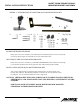
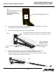
STEP 1. ATTACH THE MOUNTING ASSEMBLY TO THE BOTTOM OF THE PROJECTOR.
1.1 Place the flat surface of the 4 1/4” x 5 3/8” plate against the bottom of the
Projector with the “U” shaped cut out toward the rear of the projector.
See Fig. 2
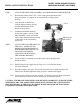
1.2 Align the plate so that the four
crescent shaped mounting slots are
over the threaded holes in the
bottom of the projector.
1.3 Install the four M4x10 mounting
Screws and washers. See Fig. 2. DO
NOT TIGHTEN. These slots will be
used to adjust the horizontal positioning
of the image on the screen during
final set up.
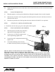
STEP 2. ATTACH THE WALL BRACKET TO
THE WALL. (REFER TO THE
PROJECTOR OWNERS MANUAL
FOR INFORMATION HELPFUL IN
LOCATING THE PROPER
LOCATION FOR MOUNTING
THE SUPPORT BRACKET.)
2.1.1 Use the bracket as a template to mark the location where the pilot holes
should be drilled.
2.1.2 Drill the holes for the support screws using a 1/8” (.125 inch) drill bit into
the center of the stud.
2.1.3 Screw the bracket to the studs. Use at least 4 hex head screws supplied with the unit.
These screws should be tightened firmly to insure a vibration free support.
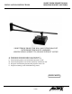
Note: Two sizes of hex head lag bolts are provided. Use shorter screws for sheetrock surfaces
and use the longer screws for walls constructed of wood lath and plaster.
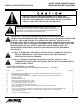
CAUTION: THE BRACKET MOUNTING SCREWS MUST GO DIRECTLY INTO THE STUDS.
SHEETROCK OR LATH AND PLASTER ALONE WILL NOT PROVIDE A SUFFICIENTLY
SECURE SUPPORT. IF THE WALL IS CEMENT BLOCK, BRICK OR SOLID MASONRY,
EXPANSION ANCHORS SHOULD BE USED.
FIG. 2
M4x10 screws
and washers