QT-CD121 SERVICE MANUAL No. S5831QTCD121/ QT-CD121 • In the interests of user-safety the set should be restored to its original condition and only parts identical to those specified should be used. CONTENTS Page IMPORTANT SERVICE NOTES ........................................................................................................................................ 2 SPECIFICATIONS .......................................................................................................................
QT-CD121 FOR A COMPLETE DESCRIPTION OF THE OPERATION OF THIS UNIT, PLEASE REFER TO THE OPERATION MANUAL. IMPORTANT SERVICE NOTES BEFORE RETURNING THE AUDIO PRODUCT (Fire & Shock Hazard) Before returning the audio product to the user, perform the following safety checks. 1. Inspect all lead dress to make certain that leads are not pinched or that hardware is not lodged between the chassis and other metal parts in the audio product. 2.
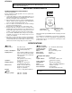
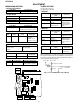
QT-CD121 NAMES OF PARTS 1. Cassette Compartment 2. CD Compartment 3. Tuning Control 4. (TAPE) Record Button: 5. (TAPE) Play Button: 6. (TAPE) Rewind Button: 7. (TAPE) Fast Forward Button: 8. (TAPE) Stop/Eject Button: / 9. (TAPE) Pause Button: 2 1 3 4 5 6 7 8 9 10 11 10. (CD) Play Indicator: 11. (CD) Track Number Indicator 12. (CD) Repeat Indicator: 13. Volume Control 14. Function Selector/Power Switch 15. Extra Bass Button: X-BASS 16. Surround Button 17. (CD) Track Down/Review Button: 18.
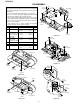
QT-CD121 DISASSEMBLY (C2)x1 Caution on Disassembly Follow the below-mentioned notes when disassembling the unit and reassembling it, to keep it safe and ensure excellent performance: 1. Take cassette tape and compact disc out of the unit. 2. Be sure to remove the power supply plug from the wall outlet before starting to disassemble the unit. 3. Take off nylon bands or wire holders where they need be removed when disassembling the unit.
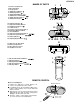
QT-CD121 REMOVING AND REINSTALLING THE MAIN PARTS CD MECHANISM SECTION Perform steps 1, 2, 3 and 5 of the disassembly method to remove the CD mechanism. (A1) x2 2.6 x6mm How to remove the pickup (See Fig. 5.) 1. Remove the screws (A1) x 2 pcs., to remove the shaft (A2) x1 pc. 2. Remove the stop washer (A3) x1 pc., to remove the gear (A4) x 1 pc. 3. Remove the pickup.
QT-CD121 ADJUSTMENT MECHANISM SECTION TUNER SECTION • Driving Force Check Torque Meter fL: Low-range frequency fH: High-range frequency Specified Value PLAY: TW-2412 • FM IF/RF Over 120 g Specified Value/Adjusting Point Test Stage • Torque Check Torque Meter Specified Value Play: TW-2111 25 to 65 g.cm Fast Forward: TW-2231 60 to 130 g.cm Rewind: TW-2231 60 to 130 g.cm • Head Azimuth Torque Meter IF T1 Detection T2 Band Coverage fL: L2 fH: TC2 Tracking 88.0 MHz: L1 108.
QT-CD121 CD SECTION Since this CD system incorporates the following automatic adjustment function, when the pickup is replaced, it is necessary to reajust it. Since this CD unit does not need adjustment, the combination of PWB and laser pickup unit is not restricted. TEST MODE Start Note Operation While holding down the "STOP" button, move the FUNCTION/POWER switch to "CD". Then, release the "STOP" button and, within 0.5 second, connect the TEST POINT to GND (within 0.5 second). (See Fig. 7) 1.
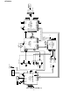
24 27 28 31 34 35 36 SEG4 57 ~ 60 SEG1 ~ 9 ~ 14 17 ~ 19 21 20 SL+ SL– +5V (D) PU-IN SW 13 14 38 25 VLC3 VDD SYSTEM MICROCOMPUTER 37 LID 23 33 22 X701 4MHz 44 30 IC701 IX0105AW 41 COM3 RX771 REMOTE SENSOR 3 2 1 RC IN COM0 RES PICKUP IN SW702 Figure 8 BLOCK DIAGRAM (1/2) –8– M702 SLIDE MOTOR M701 SPIN MOTOR TRACKING COIL FOCUS COIL PICKUP UNIT M M 17 18 26 27 11 12 1 2 30 31 1 2 3 4 SL– SL+ FIN2 FIN1 E F Q804 IC804 BA5914FP 10 19 23 25 JP– 44 43 40 32 9 EFM
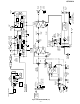
Figure 9 BLOCK DIAGRAM (2/2) –9– L-CH ERASE HEAD R-CH REC / PB HEAD FROM CD SECTION 1 L1 FM RF 2 3 9 6 FM +B SW102-H REC / PB SW102 REC / PB B.D REC / PB SW102 C,E P.B P.B R-CH 1 (AUDIO GND) 2 CD L-CH 3 +7.4V 4 +B2 5 (DIGITAL GND) 6 (POWER GND) 5 VCC MIX 8 4 7 BIAS OSC. REC P. B SW102-G REC / PB 8 6 R 12 9 R IC101 EQULIZER AMP. BA331IL L 1 REC TAPE RADIO M601 TAPE MOTOR SURROUND SW202 A,B 5 2 REG. 23 3 RF 1 22 CF 10.7MHz IC2 LA1805 FM / AM IF MPX.
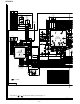
QT-CD121 SWITCH PWB-A2 SW774 TRACK DOWN/ REVIEW Q805 S9012H +B REMOTE SENSOR RX771 C849 0.022 C848 1/50 3 C779 10/16 +B C840 0.33/50 R776 10K +B SW761 CD LID OPEN/CLOSE 4 1 4 1 C835 0.1/50 SW772 STOP C837 10/16 SW771 PLAY/ REPEAT R842 22 1 C838 0.01 2 C839 1/50 SW773 TRACK UP/ CUE R779 47 B IC701 PIN VOLTAGE PIN VOLTAGE NO. NO. 0V 1 33 5V 0V 2 34 0V 0V 3 35 0V 0V 4 36 0V 0V 5 37 0.4V 0V 6 38 5V 3.9V 7 39 3.1V 0V 8 40 1.5V 5V 9 41 2.4V 10 4.1V 42 2.4V 11 4.1V 43 2.4V 12 0V 44 2.
+B F E B A K C802 47/16 R801 1K 47 44 C868 R874 10/16 100 TEST3 LVDD 36 MUTEL 35 34 DOUT 1 2 3 4 5 6 7 8 1 2 3 4 5 6 7 8 TR– TR+ FO+ FO– GND PD TR+ FO+ FO– TR+ FO+ VR LD FO– TR– TR– PICKUP UNIT C870 0.0022 R875 R876 10K 10K C867 10/16 LVSS 38 LCHO 37 C2F EMPH CONT5 CONT4 CONT3 CONT2 CONT1 B F +B +B RVSS 39 R873 100 C869 0.0022 C890 100/10 33 R880 100 24 25 26 27 28 29 30 31 32 SL+ JP– 17 18 19 20 21 22 23 K E A E A B F XL801 16.
QT-CD121 A R5 330K CF2 C28 0.0015 (Styrol) VCO AM/FM 12 C203 10/16 C35 1/50 C21 0.022 C33 1/50 C34 1/50 R13 3.9K R14 3.9K VC4 P11 7 - H TO CD SERVO/ DISPLAY SECTION C202 0.0056(ML) SW201-B CD AUTO FM AM TAPE R16 2.2K C36 0.022 C204 10/16 fH fL AM BAND COVERAGE R456 15K 1 2 3 4 5 6 R201 100K R234 4.7K R17 68 SW201-A CD AUTO FM AM TAPE R15 2.2K L4 AM OSC. R-CH AUDIO GND L-CH CD +7.4V DIGITAL GND POWER GND R203 10K R202 100K fH AM fL TRACKING TC4 R458 R457 1.2K 1.2K R233 4.
QT-CD121 6 R208 12K C210 4.7/50 5 R234 4.7K C212 100/10 7 R218 22K R216 2.2K 4 IC201-2 KIA4558S SURROUND AMP. C214 0.039 (ML) 4 C224 100/10 VOLUME 7 C225 220/25 3 R222 1K C222 0.0015 11 C232 0.1 (ML) 9 – + 10 6 C220 0.047 (ML) 5 J201 HEADPHONES 1 2 2 3 3 SP502 IC202 PIN VOLTAGE NO. 0.1V 1 0V 2 11.2V 3 0V 4 11.3V 5 0V 6 0.1V 7 12V 8 10.4V 9 10 5.8V 11 0V 12 5.8V 13 10.4V C234 1000/10 8 D201 1N4148 1 SPEAKERS SP501 L-CH C231 0.
QT-CD121 HEADPHONES PWB-A4 R352 R106 R102 C106 R116 R114 R122 CNP602 R124 C844 C889 ZD801 R810 C849 R820 C815 R819 C811 C812 R816 C814 R815 R814 R828 R817 C848 E C B 12 10 1 8 C807 C809 R812 R806 C808 R807 R811 R809 R808 C810 5 1 CNS802 BK WH WH WH WH 5 BI802 R805 C806 C804 R803 R802 R804 C805 1 C801 C802 16 10 C839 BR BK 1 BK 2 3 BK 4 BK 5 BK 6 BK 7 BK 8 Q805 17 C803 C850 C813 20 15 IC801 55 C840 R842 R830 R840 C816 R839 R821 C822 25 64 CNS801 8 BI801
QT-CD121 SPEKERS SP502 R-CH SP501 L-CH COLOR TABLE BR CNS201 SW601 TAPE MAIN (241-7) 1 WH 2 BK 3 RD M601 TAPE MOTOR (241-6) TAPE ERASE HEAD (241-5) RED OR ORANGE YL YELLOW GR GREEN BL BLUE VL VIOLET GY GRAY WH(W) WHITE BK BLACK PK PINK RD BK BR WH YL RECORD/PLAYBACK HEAD(241-4) BROWN RD(R) BK CNS101 4 3 2 1 BK WH RD BK BK (211) T601 POWER TRANSFORMER TERMINAL PWB-A3 + BATTERYS DC12V["D"SIZE(UM/SUM-1, R20 or HP2)battery 8] C653 (236) RD D653 D652 RD C652 C654 2 1
QT-CD121 NOTES ON SCHEMATIC DIAGRAM • Resistor: To differentiate the units of resistors, the symbol as K and M are used: the symbol K means 1000 ohm and the symbol M means 1000 kohm and the resistor without any symbol is an ohm resistor. The resistor designated "Fusible" is a fuse type resistor • Capacitor: To indicate the unit of capacitor, a symbol P is used: this symbol P means micro-micro-farad and the unit of the capacitor without such a symbol is microfarad.
QT-CD121 WAVEFORMS OF CD CIRCUIT 1 2 5ms 0.50 V IC801 20 F.E 5ms 5.0 V IC801 54 DRF STOP FOCUS PLAY SERCH 50ms 10.0 V JP+ 7 50ms 10.0 V JP- 8 50ms 0.50 V JP 9 50ms 1.00 V TE 6 0.5ms 10.0 V JP+ 7 0.5ms 10.0 V JP- 8 0.5ms 0.50 V JP 9 0.5ms 1.00 V TE 10 20ms 1.00 V SPO 11 20ms 2.00 V CLV+ 10 50ms 1.00 V SPO 11 50ms 2.00 V CLV+ 3 1 3 6 CUE 0.5ms 1.00 V HF 1 4 0.5ms 5.0 V HFL 5 0.5ms 5.0 V TES 3 0.5ms 1.00 V H.F 4 0.5ms 5.0 V HFL 5 0.5ms 5.
QT-CD121 TROUBLESHOOTING When the CD does not function When the CD section does not operate When the objective lens of the optical pickup is dirty,this section may not operate.Clean the objective lens,and check the playback operation.When this section does not operate even after the above step is taken,check the following items. Remove the cabinet and follow the troubleshooting instructions.
QT-CD121 • Playback can only be performed when a disc is loaded. No Check the laser diode driver. Check the area around IC801(16) - (21) (focus servo circuit). No If the disc is not turning, the DRF should not change to "H". Is the Focus servo active? (Can you hear it working?) Yes ▼ Yes Does the DRF signal change from "L" to "H"? Check the spin system. Yes Yes No Level is abnormal. ▼ Is HF waveform normal (see the Fig. 19-1, 2)? Yes Check the periphery of IC801 pins 41 and 42.
QT-CD121 • Checking the spin system. Play operation is performed without disc. Yes The spin driver circuit is normal. The turntable rotates a little. Yes No The turntable fails to rotate or rotates at high speed. Yes Check the periphery of IC801 pins 23 to 27, pin 39 and pin 40, IC802 pin 12 and pin 13, IC804 to BI803/CNS803. • Checking the VCO-PLL system Play operation is performed when disc exits. Yes Although HF waveform is normal, TOC data cannot be read. Yes Check PDO waveform (Fig. 20).
QT-CD121 FUNCTION TABLE OF IC IC701 RH-iX0105AWZZ (IX0105AW): System Control Microcomputer Pin No. Terminal Name Port Name Input/ Output Function 1* P03 MTCONT2 Input/Output Used to input or output 4 bits at a time. When the output latch is set to "1", the unit will be in the input mode. The key-on wakeup function, which can be switched on or off by the software, and a pull-up transistor, which can be turned on or off by the software, are built in.
QT-CD121 —MEMO— – 22 –
QT-CD121 PARTS GUIDE MODEL QT-CD121 “HOW TO ORDER REPLACEMENT PARTS” To have your order filled promptly and correctly, please furnish the following information. 1. MODEL NUMBER 2. REF. No. 3. PART NO. 4. DESCRIPTION For U.S.A. only Contact your nearest SHARP Parts Distributor to order. For location of SHARP Parts Distributor, Please call Toll-Free; 1-800-BE-SHARP MARK: SPARE PARTS-DELIVERY SECTION Explanation of capacitors/resistors parts codes Capacitors Resistors VCC .......................
QT-CD121 NO. PRICE RANK PART CODE DESCRIPTION INTEGRATED CIRCUITS IC1 IC2 IC101 VHILA1186N/-1 VHILA1805//-1 VHIBA3311L/-1 J J J IC201 IC202 IC203 IC701 VHIKIA4558S-1 VHILA4597//-1 VHIKIA7808P-1 RH-IX0105AWZZ J J J J IC801 IC802 IC804 VHILA9241M/-1 VHILC78623D-1 VHIBA5914FP-1 J J J AE FM Front End,LA1186N AM FM/AF IF MPX.,LA1805 AK REC./P.B.Equalizer Amp., BA3311L AK Surround Amp.,KIA4558S AH Power Amp.,LA4597 AH Voltage Regulator,KIA7808P BA System Microcomputer, IX0105AW AS Servo Amp.
QT-CD121 NO.
QT-CD121 NO.
QT-CD121 306 701 A 704 304 701 B 302 702 C 301 303 D 703x2 E M701 F 305 M702 305x2 G SW702 H PWB-B 1 2 3 4 Figure 4 CD MECHANISM EXPLODED VIEW ––27 4 –– 5 6
QT-CD121 203 213 601x3 A 215 212 242 PWB-A3 B 211 236 602x6 214 601x2 221 PWB-A5 231 601 603 603 603x2 C 230x2 603 202 PWB-A4 603 601x2 TAPE MECHANISM 241 (241-1, 241-2 241-3, 241-4, 241-5, 241-6, 241-7) D 232-2 222 228 227 226 225 229 220 204 CD MECHANISM 602 606 223 216 SW761 224 603x4 608 607x2 603 603 234 E 205 Silicon Grease 605x3 603x4 607 604x3 SP503 SP501 201 F 232-1 232 607 PWB-A1 218 238 219 243 603x2 603 217 235 G PWB-A2 207 603x5 LCD701
QT-CD121 PACKING OF THE SET • Setting position of switches and knobs Tape Mechanism Control STOP STATE TUNING LOW POWER/FUNCTION OFF/TAPE X-BASS OFF SURROUND OFF VOLUME LOW Remote Control AC Power Supply Cord Polyethylene Bag, Unit SSAKH0001SJZZ Packing Case SPAKC0003SJZZ Feature Label FR ON T Operation Manual FR ON T Packing Add.
QT-CD121 —MEMO— ––30 7 ––
QT-CD121 —MEMO— ––31 8 ––
QT-CD121 COPYRIGHT © 1998 BY SHARP COPORATION ALL RIGHTS RESERVED. No part of this publication may be reproduced, stored in a retrieval system, or transmitted in any from or by any means, electronic, mechanical, photocopying, recording, or otherwise, without prior written permission of the publisher.