
Service manual

5
R-209EKA
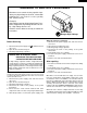
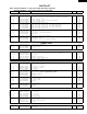
SCHEMATIC
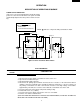
NOTE: CONDITION OF OVEN
1. DOOR CLOSED
2. CLOCK APPEARS ON DISPLAY
NOTE: " " indicates components with potential above 250V.
POWER
TRANSFORMER
RECTIFIER
MAGNETRON
CAPACITOR
0.86µF
C/T FUSE
120V AC
60 Hz
OVEN
LAMP
TURN-
TABLE
MOTOR
FAN
MOTOR
MONITOR
SWITCH
SECONDARY
INTERLOCK
SWITCH
TTM
OL FM
GRN
A3
COM.
N.O.
DOOR
SENSING
SWITCH
B1 B2
(RY-1)
(RY-2)
CONTROL UNIT
PRIMARY
INTERLOCK
RELAY
MAGNETRON
THERMAL CUT-OUT
A1
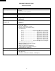
TEST PROCEDURES
PROCEDURE
LETTER
COMPONENT TEST
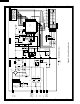
Figure O-1. Oven Schematic-Off Condition
OPERATION
DESCRIPTION OF OPERATING SEQUENCE
POWER OUTPUT REDUCTION
If the oven is set for more than 20 minutes at 80, 90 or 100%
power level, after the first 20 minutes the power level will
automatically adjust itself to 70% power to avoid overcook-
ing.
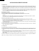
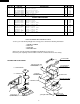
B POWER TRANSFORMER TEST
1. Disconnect the power supply cord, and then remove outer case.
2. Open the door and block it open.
3. Discharge high voltage capacitor.
4. Disconnect the primary input terminals and measure the resistance of the transformer with an
ohmmeter. Check for continuity of the coils with an ohmmeter. On the R x 1 scale, the resistance of
the primary coil should be less than 1 ohm and the resistance of the high voltage coil should be
approximately 132 ohms; the resistance of the filament coil should be less than 1 ohm.
5. Reconnect all leads removed from components during testing.
6. Reinstall the outer case (cabinet).
7. Reconnect the power supply cord after the outer case is installed.
8. Run the oven and check all functions.
(HIGH VOLTAGES ARE PRESENT AT THE HIGH VOLTAGE TERMINAL, SO DO NOT ATTEMPT TO
MEASURE THE FILAMENT AND HIGH VOLTAGE.)