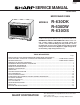
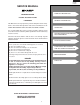
R - 630DK R -630 DW R - 630 DS SERVICE MANUAL S7017R630DPW/ MICROWAVE OVEN MODELS Breakfast Linch on One Dish Bar the Run Dinners Popcorn Baked Sensor Potatoes Reheat Custom More from your Microwave Help Sensor Cooking Super Compu Defrost Defrost Beverage Vegetables Main Frozen center Kitchen Entrees Foods Timer/Clock 1 2 3 4 5 Power Level Minute PLus 6 7 8 9 0 STOP Clear START Touch on R-630DK R-630DW R-630DS In the interest of user-safety the oven should be restored to its original condi
R -630DK R-630DW R -630DS PRECAUTIONS TO BE OBSERVED BEFORE AND DURING SERVICING TO AVOID POSSIBLE EXPOSURE TO EXCESSIVE MICROWAVE ENERGY (a) Do not operate or allow the oven to be operated with the door open.
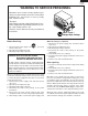
R -630DK R-630DW R -630DS WARNING TO SERVICE PERSONNEL Microwave ovens contain circuitry capable of producing very high voltage and current, contact with following parts may result in a severe, possibly fatal, electrical shock. (Example) High Voltage Capacitor, High Voltage Power Transformer, Magnetron, High Voltage Rectifier Assembly, High Voltage Harness etc.. Read the Service Manual carefully and follow all instructions. Don't Touch ! Danger High Voltage When the testing is completed, 1.
R- 630DK R-630DW R -630 DS MICROWAVE MEASUREMENT PROCEDURE A. Requirements: 1) Microwave leakage limit (Power density limit): The power density of microwave radiation emitted by a microwave oven should not exceed 1mW/cm2 at any point 5cm or more from the external surface of the oven, measured prior to acquisition by a purchaser, and thereafter (through the useful life of the oven), 5 mW/cm2 at any point 5cm or more from the external surface of the oven.
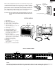
R -630DK R-630DW R -630DS SERVICE MANUAL PRODUCT DESCRIPTION MICROWAVE OVEN R-630DK/ R-630DW/ R-630DS GENERAL INFORMATION FOREWORD This Manual has been prepared to provide Sharp Electronics Corp. Service Personnel with Operation and Service Information for the SHARP MICROWAVE OVEN, R-630DK, R-630DW, R-630DS. It is recommended that service personnel carefully study the entire text of this manual so that they will be qualified to render satisfactory customer service.
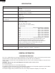
R- 630DK R-630DW R -630 DS SPECIFICATION ITEM DESCRIPTION Power Requirements 120 Volts / 14 Amperes 60 Hertz Single phase, 3 wire grounded Power Output 1100 watts (IEC TEST PROCEDURE) Operating frequency of 2450MHz Width 19-1/2" Height 14" Depth 20-5/8" Width 17-3/4" Height 8-1/4" Depth 17" Case Dimensions Cooking Cavity Dimensions 1.4 Cubic Feet Control Complement Touch Control System Clock ( 1:00 - 12:59 ) Timer (0 - 99 min. 99 seconds) Microwave Power for Variable Cooking Repetition Rate; P-HI .
R -630DK R-630DW R -630DS Where a two-pronged wall-receptacle is encountered, it is the personal responsibility and obligation of the customer to contact a qualified electrician and have it replaced with a properly grounded three-pronged wall receptacle or have a grounding adapter properly grounded and polarized. If the extension cord must be used, it should be a 3-wire, 15 amp. or higher rated cord. Do not drape over a countertop or table where it can be pulled on by children or tripped over accidentally.
R- 630DK R-630DW R -630 DS OPERATION DESCRIPTION OF OPERATING SEQUENCE (1) When the door opens from the closed position, the primary interlock relay (RY2) and secondary interlock switch open their contacts. And contacts of the relay (RY1) remains closed. Then the monitor switch contacts close. (2) When the door is closed from the open position, the monitor switch contacts open first. Then the contacts of the secondary interlock switch and door sensing switch close. And contacts of the relay (RY1) open.
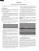
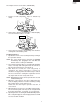
R -630DK R-630DW R -630DS An example of how sensor works: (POTATOES) 1. Potates at room temperature. Vapor is emitted very slowly. MIC RO WA VE 2. Heat Potates. Moisture and humidity is emitted rapidly. You can smell the aroma as it cooks. AH SENSOR MIC RO WA VE 3. Sensor detects moisture and humidity and calculates cooking time and variable power. Cooking Sequence. 1. Operate the oven in sensor cooking mode by referring to the operation manual.
R- 630DK R-630DW R -630 DS SCHEMATIC NOTE: CONDITION OF OVEN 1. DOOR CLOSED 2. CLOCK APPEARS ON DISPLAY MONITOR FUSE 20A THERMAL CUT-OUT (OVEN) THERMAL CUT-OUT (MG.) N.O. POWER TRANSFORMER N.O. F3 A2 CAPACITOR 0.94µF AC 2200V F2 F1 PRIMARY INTERLOCK RELAY AH SENSOR (RY-2) (RY-1) A1 CONTROL UNIT COM. COM. B2 GRN 120V AC 60 Hz B1 DOOR SENSING SWITCH OL OVEN LAMP TTM MONITOR SWITCH FM RECTIFIER MAGNETRON SECONDARY INTERLOCK SWITCH TURNTABLE MOTOR FAN MOTOR Figure O-1.
R -630DK R-630DW R -630DS DESCRIPTION AND FUNCTION OF COMPONENTS DOOR OPEN MECHANISM CAUTION: BEFORE REPLACING A BLOWN MONITOR FUSE TEST THE DOOR SENSING SWITCH, PRIMARY INTERLOCK RELAY (RY2), RELAY (RY1), SECONDARY INTERLOCK SWITCH AND MONITOR SWITCH FOR PROPER OPERATION. (REFER TO CHAPTER "TEST PROCEDURE"). NOTE: MONITOR FUSE AND MONITOR SWITCH ARE REPLACED AS AN ASSEMBLY. The door is opened by pulling the door. Refer to the Figure D-1.
R- 630DK R-630DW R -630 DS TROUBLESHOOTING GUIDE Never touch any part in the circuit with your hand or an uninsulated tool while the power supply is connected. When troubleshooting the microwave oven, it is helpful to follow the Sequence of Operation in performing the checks. Many of the possible causes of trouble will require that a specific test be performed. These tests are given a procedure letter which will be found in the "Test Procedure "section.
R -630DK R-630DW R -630DS CK = Check / RE = Replace Home fuse or circuit breaker blows when power cord is plugged into wall receptacle Monitor fuse blows when power cord is plugged into wall receptacle. OFF CONDITION All letters and indicators do not appear in display when power cord is first plugged into wall outlet. Display does not operate properly when STOP/CLEAR key is touched. (Buzzer should sound and ":" or time of day should appear in display.) Oven lamp does not light when door is opened.
R- 630DK R-630DW R -630 DS TEST PROCEDURES PROCEDURE LETTER A COMPONENT TEST MAGNETRON ASSEMBLY TEST 1. 2. 3. 4. 5. 6. 7. 8. 9. Disconnect the power supply cord, and then remove outer case. Open the door and block it open. Discharge the high voltage capacitor. To test for an open filament, isolate the magnetron from the high voltage circuit. A continuity check across the magnetron filament leads should indicate less than 1 ohm.
R -630DK R-630DW R -630DS TEST PROCEDURES PROCEDURE LETTER COMPONENT TEST (HIGH VOLTAGES ARE PRESENT AT THE HIGH VOLTAGE TERMINAL, SO DO NOT ATTEMPT TO MEASURE THE FILAMENT AND HIGH VOLTAGE.) C HIGH VOLTAGE RECTIFIER TEST 1. 2. 3. 4. Disconnect the power supply cord, and then remove outer case. Open the door and block it open. Discharge the high voltage capacitor. Isolate the rectifier from the circuit.
R- 630DK R-630DW R -630 DS TEST PROCEDURES PROCEDURE LETTER COMPONENT TEST 5. Reconnect all leads removed from components during testing. 6. Reinstall the outer case (cabinet). 7. Reconnect the power supply cord after the outer case is installed. 8. Run the oven and check all functions. CAUTION: IF THE THERMAL CUT-OUT INDICATES AN OPEN CIRCUIT AT ROOM TEMPERATURE, REPLACE THERMAL CUT-OUT. F SECONDARY INTERLOCK SWITCH TEST 1. 2. 3. 4. 5. 6. 7. 8.
R -630DK R-630DW R -630DS TEST PROCEDURES PROCEDURE LETTER COMPONENT TEST 5. 6. 7. 8. actuator is pushed by a screw driver through the lower latch hole on the front plate of the oven cavity with the door opened (in this condition the plunger of the monitor switch is pushed in), the meter should indicate an open circuit. If improper operation is indicated, the switch may be defective.
R- 630DK R-630DW R -630 DS TEST PROCEDURES PROCEDURE LETTER COMPONENT TEST 2-1 In connection with pads. a) When touching the pads, a certain group of pads do not produce a signal. b) When touching the pads, no pads produce a signal. 2-2 In connection with indicators a) At a certain digit, all or some segments do not light up. b) At a certain digit, brightness is low. c) Only one indicator does not light. d) The corresponding segments of all digits do not light up; or they continue to light up.
R -630DK R-630DW R -630DS TEST PROCEDURES PROCEDURE LETTER COMPONENT TEST 6. After that procedure, re-connect the power supply cord. 7. Remove the outer case and check voltage between Pin No. 1 of the 2 pin connector (A) and the normal open terminal of the relay RY1 on the control unit with an A.C. voltmeter. The meter should indicate 120 volts, if not check oven circuit. RY1 and RY2 Relay Test These relays are operated by D.C. voltage Check voltage at the relay coil with a D.C.
R- 630DK R-630DW R -630 DS TEST PROCEDURES PROCEDURE LETTER COMPONENT TEST RY2 RY1 c T1 (J1) 1 6) Reconnect all leads removed from components AC during testing. 7) Re-install the outer case (cabinet). 8) Reconnect the power supply cord after the outer case is installed. 9) Run the oven and check all functions. 2. Follow the troubleshooting guide given below, if the indicator does not light up after above check and repairs are finished. 1) Disconnect the power supply cord, and then remove outer case.
R -630DK R-630DW R -630DS TEST PROCEDURES PROCEDURE LETTER COMPONENT TEST WARNING : The oven should be fully assembled before following procedure. Make sure the oven has been plugged in at least two minutes before checking sensor cook operation. The cabinet should be installed and screws tightened. (1) Fill approximately 200 milliliters (7.2 oz) of tap water in a 1000 milliliter measuring cup. (2) Place the container on the center of tray in the oven cavity. (3) Close the door.
R- 630DK R-630DW R -630 DS TEST PROCEDURES PROCEDURE LETTER COMPONENT TEST (11) Open the door and block it open. (12) Discharge high voltage capacitor. (13) Disconnect the dummy resistor circuit from the sensor connector of control panel. (14) Carry out necessary repair. (15) Reconnect all leads removed from components during testing and repairing. (16) Re-install the outer case (cabinet). (17) Reconnect the power supply cord after the outer case is installed. Run the oven and check all functions.
R -630DK R-630DW R -630DS LSI(IXA054DR) The I/O signal of the LSI(IXA054DR) is detailed in the following table. Pin No. Signal I/O Description 1 AN10 IN Signal coming from touch key. When either G10 line on key matrix is touched, a corresponding signal out of P10 - P17 will be input into ANI0. When no key is touched, the signal is held at "H" level. 2 AN11 IN Signal similar to AN10. When either G9 line on key matrix is touched, a corresponding signal will be input into AN11.
R- 630DK R-630DW R -630 DS Pin No. Signal I/O 23 P24 OUT Description Oven lamp, fan motor and turntable motor driving signal To turn on and off shut off relay (RY1). The 16.7 msec. square waveform voltage is delivered to the RY1 driving circuit and RY2 control circuit. H : GND L : -5V During cooking 24 P25 OUT Magnetron high-voltage circuit driving signal. OFF H : GND 100 To turn on and off the cook relay (RY2).
R -630DK R-630DW R -630DS Pin No. Signal I/O Description 95-98 AN4-AN7 IN Terminal to change cooking input according to the Model. By using the A/D converter contained in the LSI, DC voltage in accordance with the Model in operation is applied to set up its cooking constant. 99 AN8 IN Signal similar to ANI7. When either G12 line on key matrix is touched, a corresponding signal will be input into AN8. 100 AN9 IN Signal similar to ANI7.
R- 630DK R-630DW R -630 DS TOUCH CONTROL PANEL SERVICING 4) Re-install the outer case (cabinet). 5) Re-connect the power supply cord after the outer case is installed. 6) Run the oven and check all functions. A. On some models, the power supply cord between the touch control panel and the oven itself is so short that the two can’t be separated. For those models, check and repair all the controls (sensor-related ones included) of the touch control panel while keeping it connected to the oven. B.
R -630DK R-630DW R -630DS COMPONENT REPLACEMENT AND ADJUSTMENT PROCEDURE WARNING AGAINST HIGH VOLTAGE: Microwave ovens contain circuitry capable of producing very high voltage and current, contact with following parts may result in severe, possibly fatal, electric shock. (Example) High Voltage Capacitor, Power Transformer, Magnetron, High Voltage Rectifier Assembly, High Voltage Harness etc.. WARNING: Avoid possible exposure to microwave energy.
R- 630DK R-630DW R -630 DS 7. Lift entire outer case from the unit. CAUTION: 1. DISCONNECT OVEN FROM POWER SUP PLY BEFORE REMOVING OUTER CASE. 2. DISCHARGE THE HIGH VOLTAGE CAPACITOR BEFORE TOUCHING ANY OVEN COMPONENTS OR WIRING. NOTE: When replacing the outer case, the 2 special Torx screws must be reinstalled in the same locations.
R -630DK R-630DW R -630DS 3. Discharge the high voltage capacitor. 4. Disconnect the high voltage wire B from the power transformer. 5. Disconnect the high voltage wire of the high voltage rectifier assembly from the magnetron. 6. Disconnect the filament lead (short one) of the power transformer from the high voltage capacitor. 7. Remove one (1) screw holding capacitor holder to base plate. 8. Remove one (1) screw holding high voltage rectifier assembly to capacitor holder. 9.
R- 630DK R-630DW R -630 DS 12.Remove the fan motor with the fan motor mounting angle from the fan case assembly and the cross flow fan. 13.Remove the two (2) screws holding the fan motor mounting angle to the fan motor. 14.Now, the fan motor is free. TURNTABLE MOTOR REMOVAL 1. Disconnect the power supply cord. 2. Remove turntable and turntable support from oven cavity. 3. Lay the oven on it's backside. Remove the turntable motor cover by snipping off the material in four corners. 4.
R -630DK R-630DW R -630DS DOOR SENSING SWITCH/SECONDARY INTERLOCK SWITCH AND MONITOR SWITCH ADJUSTMENT the latched position. First check upper position of latch hook, pushing and pulling upper portion of door toward the oven face. Then check lower portion of the latch hook, pushing and pulling lower portion of the door toward the oven face. Both results (play in the door) should be less than 0.5mm. 2. The contacts of door sensing switch and secondary interlock switch open within 1.
R- 630DK R-630DW R -630 DS Note: The door on a microwave oven is designed to act as an electronic seal preventing the leakage of microwave energy from oven cavity during cook cycle. This function does not require that door be air-tight, moisture (condensation)-tight or light-tight. Therefore, occasional appearance of moisture, light or sensing of gentle warm air movement around oven door is not abnormal and do not of themselves indicate a leakage of microwave energy from oven cavity.
R -630DK R-630DW R -630DS PWB Cover Tabs Tabs Door screen wire harness Tabs Tabs Tabs Figure C-10. Routing of wire harness NOTE: For key sheet 1. Before attaching a new key sheet, wipe off remaining adhesive on the door screen surfaces completely with a soft cloth soaked in alcohol. 2. When attaching the key sheet to the door screen, adjust the upper edge and left edge of the key sheet to the correct position of door screen. 3.
1 2 3 4 32 BLK 5 H 6 BLU/ 12 GRN 1 3 CN-F 12 CN-F 1 BLK 2 RED 3 WHT CN-B 3 GRY 2 1 GRN AH SENSOR POWER UNIT CN-C 2 Figure S-1. Pictorial Diagram FAN MOTOR BLK BLK GRY WHT BLK MONITOR FUSE & HOLDER BLK WHT TURNTABLE MOTOR BLK THERMAL CUT-OUT (OVEN) BLK MAGNETRON N.C. COM. GRY GRN WHT GRY WHT WHT WHT COM. BLK YLW THERMAL CUT-OUT (MG) N.O. SECONDARY NO INTERLOCK SWITCH MONITOR SWITCH RED COM.
R -630DK R-630DW R -630DS 2 1 4 3 6 5 A A B B + – + – C3 10µ/35v b ZD1 HZ16-1 4 NO MICRO 6 R53 1.8kF 8 4 VA C1 INT C5 VR F-1 F-3 B-2 CN-B D C4 BUZZER C8 AH E B-1 F-2 F C6 R54 360kF COM DOOR SENSING SWITCH GND2 7 R50 330 1w RY2 5 C51 0.1µ/50v COM IC2 BA4558 C50 0.1µ/50v R51 3.32kD NO SP1 PKM22EPT R52 3.57kD RY1 E C7 R2 680 1/2w D OVEN LAMP TURNTABLE MOTOR FAN MOTOR GND1 C c AC C10 Q1 2SB1238 (J1) a 1 R1 2.4k d C CN-C D1 S1NB10 C2 0.
C8 C4 C9 C6 AH BUZZER VA 3 34 C2 C11 C12 DOOR LD10 LD11 LD12 LD13 NOTE R30 3.3k 4 Q21 DTD143EKA JA C20 Q20 0.1µ/50v DTA143EKA Q30 DTA143EKA Q10 DTA143EKA Q22 DTA123JKA – + : IF NOT SPECIFIED 1/10W ± 5% D40 MA152WA D20 MA152WA R31 3.3k LD19 R104 680 1/2w Q1 KTA1661 R5 1k ZD1 UDZ4.3B R41 15k C4 0.01µ/25v R6 15k D90 MA152WA Q2 2SA1037AK 5 R71 15k R70 15k (J16) (J17) 4.7k R97 47k R95 47k R111 4.7k 1 IC1 IXA054DR 5 C60 330pF/50v C61 330pF/50v (J12) (J13) 4.
C124 0.
R- 630DK R-630DW R -630 DS 1 14 1 D1 (D8) 7 1 S T1 6 2 5 P VRS1 4 3 2 1 CN - A 6 5 F F DIP CN - C 8 OM DU RY2 MICRO AC CN - F 1 C2 SP1 3 (D9) R54 CN - B (D7) 1 (J1) 36 C50 JX JY R53 R51 R52 (C52) 1 CN - H C51 E C B 2 OL,TTM,FM RY1 DU 4 3 2 1 E E R50 C3 Q1 OM 2 1 D D IC2 R2 R1 C1 ZD1 C C B B 6 5 4 3 2 1 A A G G H H Figure S-5.
R - 630DK R -630 DW R - 630 DS PARTS LIST Note: The parts marked “ ∆” may cause undue microwave exposure. The parts marked “*” are used in voltage more than 250V. REF. NO. PART NO.
R -630DK R-630DW R -63 0 DS ∆ REF. NO. 4-10 4-11 4-12 4-13 4-14 4-15 4-16 4-17 4-18 4-19 4-20 4-21 4-22 4-23 4-24 4-25 4-26 4-27 4-28 4-29 4-30 PART NO.
R - 630DK R -630 DW R - 630 DS REF. NO. 7- 3 7- 4 7- 5 7- 6 7- 7 7- 8 7- 9 7-10 7-11 7-12 7-13 7-14 7-14 7-14 7-15 7-16 7-17 7-18 PART NO.
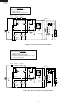
R -630DK R-630DW R -63 0 DS 2 1 4 3 6 5 7-13 OVEN AND CABINET PARTS 7-18 2-4 4-23 A A 1-15 7-5 7-14 4-26 4-17 7-8 B B 1-13 6-8 7-12 6-9 4-12 4-24 1-1 4-28 C 7-14 7-3 4-18 4-27 4-30 C 6-7 7-3 7-11 6-6 7-3 4-11 4-19 7-3 D 7-3 4-14 7-11 D 7-11 7-5 4-15 A 4-16 4-10 1-10 7-10 1-11 7-17 1-12 6-13 7-9 7-11 4-9 4-20 1-5 7-11 E 1-3 1-14 1-8 7-11 7-3 E 4-4 7-11 7-1 1-4 4-1 7-11 7-15 4-7 7-2 2-6 F 1-3 4-25 2-5 7-4 4-21 4-6 7-7 F 7-11 1-4 1-6 7
R - 630DK R -630 DW R - 630 DS 2 1 4 3 6 5 5-13 A A 5-13 DOOR PARTS 5-20 5-10 5-11 5-9 5-17 5-12 5-14 4-13 5-13 5-2 5-11 B 5-12 B 5-12 5-1 5-21 C C 5-12 5-6 5-19 5-21 5-18 5-15 5-4 D D 5-16 5-7 5-8 5-3-1 5-3 MISCELLANEOUS E E 5-5 6-3 Actual wire harness may be different from illustration.
R -630DK R-630DW R -63 0 DS COPYRIGHT © 2000 BY SHARP CORPORATION ALL RIGHTS RESERVED. No part of this publication may be reproduced, stored in retrieval systems, or transmitted in any form or by any means, electronic, mechanical, photocopying, recording, or otherwise, without prior written permission of the publisher. 2000 SHARP CORP. (7S2.530E) Printed in U.S.