INSTRUCTIONS–PARTS LIST 306–518 Rev. R Supersedes N and PCN P This manual contains important warnings and information. READ AND RETAIN FOR REFERENCE 5:1 Ratio Fire-Ball Pumps 900 psi (62 bar) Maximum Working Pressure 180 psi (12 bar) Maximum Air Input Pressure Gear Lube and Motor Oil Pumps (See page 5 for pump models and descriptions) MODEL 203–872 MODEL 203–876 Table of Contents Warnings . . . . . . . . . . . . . . . . . . . . . . . . . . . . . . . . . . . . . .
Symbols Warning Symbol Caution Symbol WARNING CAUTION his symbol alerts you to the possibility of serious injury or death if you do not follow the instructions. This symbol alerts you to the possibility of damage to or destruction of equipment if you do not follow the instructions. WARNING WARNING EQUIPMENT MISUSE HAZARD Equipment misuse can cause the equipment to rupture or malfunction and result in serious injury. D This equipment is for professional use only.
WARNING WARNING FLUID INJECTION HAZARD Spray from the dispensing valve, leaks or ruptured components can inject fluid into your body and cause extremely serious injury, including the need for amputation. Fluid splashed in the eyes or on the skin can also cause serious injury. If a fluid injection injury occurs, get emergency medical care at once. Do not treat as a simple cut. Tell the doctor exactly what fluid was injected. NOTE TO PHYSICIAN: Injection into the skin is a traumatic injury.
WARNING WARNING FIRE AND EXPLOSION HAZARD Improper grounding, poor ventilation, open flames or sparks can cause a hazardous condition and result in a fire or explosion and serious injury. Ground the equipment and the object being sprayed. Refer to Grounding on page 8. If there is any static sparking or you feel an electric shock while using this equipment, stop spraying immediately. Do not use the equipment until you identify and correct the problem.
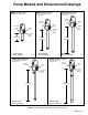
Pump Models and Dimensional Drawings MODEL 203–876, Series K Stubby size, wall mount MODEL 203–857, Series K 55 gal. (400 lb) drum size, cover mount MODEL 203–872, Series K 16 gal. (120 lb) drum size, cover mount 3/8 npt(f) Air Inlet 3/8 npt(f) Air Inlet Grndg Lug Grndg Lug 3/8 npt(f) Air Inlet Grndg Lug 1/2 npt(f) Fluid Outlet 1/2 npt(f) Fluid Outlet 11 in. (279 mm) 33.7 in. (856 mm) 26.7 in. (678 mm) Overall length: 22.8 in. (579 mm) 04109 1/2 npt(f) Fluid Outlet Overall length: 38.5 in.
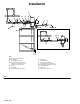
Installation G A C A N D F E P H B J DETAIL A Q M L K 04115 1/2 in. (13 mm) KEY A B C D E F G Bleed-Type Master Air Valve Air Line Filter Air Regulator and Gauge Pump Runaway Valve (shown for position – not needed if you use a low level cut-off valve [K]) Air Inlet Ground Wire Pump (Model 204–254 shown) Fig.
Installation The installation shown in Fig.1 is only a guide to selecting and installing optional and required accessories. For assistance in designing a system to suit your needs, contact your Graco representative or Graco Technical Assistance at 1–800–543–0339. Install the pump on the drum cover so the pump’s fluid intake is 1/2 in. (13 mm) off the bottom of the drum.
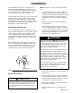
Installation Grounding To ground the pump: Proper grounding is an essential part of maintaining a safe system. To ground the pump, loosen the grounding lug locknut (W) and washer (X). Insert one end of a 12 ga (1.5 mm ) minimum ground wire (Y) into the slot in lug (Z) and tighten the locknut securely. Connect the other end of the wire to a true earth ground. Order Part No. 222–011, Ground Wire and Clamp. To reduce the risk of static sparking, ground the pump.
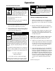
Operation Pressure Relief Procedure WARNING PRESSURIZED FLUID HAZARD The equipment stays pressurized until pressure is manually relieved. to reduce the risk of serious injury from pressurized fluid, accidental spray from the valve or splashing fluid, follow this procedure whenever you: Are instructed to relieve pressure Stop dispensing Check, clean or service any system equipment Install or clean dispensing devices 1.
Operation NOTE: The low level cut-off valve accessory (K) closes the pump fluid intake when the fluid level is low, causing the pump to stall, to avoid running dry. 6. Read and follow the instructions supplied with each component in your system. A pump runaway valve (D) can be installed on the air line of pumps not equipped with a low level cut-off valve, to automatically shut off the pump if it starts to run too fast. 7.
Air Motor and Throat Service Before you start: 1. Be sure you have all necessary parts on hand. Air Motor Repair Kit 206–728 includes repair parts for the motor. Use all the parts in the kit for the best results. Parts included in the kit are marked with one asterisk, for example (28*), in the t ext and drawings. See the Parts List for your pump model number. 2. Displacement Pump Repair Kit 237–498 includes repair parts for the pump throat and piston. Use all the parts in the kit for the best results.
Air Motor and Throat Service WARNING MOVING PARTS HAZARD To reduce the risk of pinching or amputating your fingers, always keep fingers clear of the toggle assemblies (M). Reassembly 1. Clean all the parts carefully in a compatible solvent and inspect for wear or damage. Use all the repair kit parts during reassembly and replace other parts as necessary. 2. Check the polished surfaces of the piston, piston rod and cylinder wall for scratches or wear.
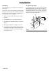
Air Motor and Throat Service 51 24 M 1 2 35 32* 30* 27 26 51 42* 28* 3 50* 55 42* 33 30* L 28* 30* 34* 49 4 56 52 49* 56 55 50 30* Cutaway View 04119 04118 1 Push toggles (M) in and then up. 2 Cut off tops of poppets as indicated by dotted lines. 3 Turn wires up. 0.145 in. (3.7 mm) clearance between poppets (49*) and seat when it is open. 4 Fig.
Displacement Pump Service Disassembly NOTE: Displacement Pump Repair Kit 237–498 includes repair parts for the pump piston and throat. Parts included in the kit are marked with two asterisks, for example, (6 ), in the text and drawings. 1. Flush the pump. Follow the Pressure Relief Procedure on page 9, before proceeding. 2. Disconnect the hoses, remove the pump from its mounting, and clamp the air motor base in a vise. 3. Unscrew the intake valve body (61 or 65) from the displacement cylinder (16).
Displacement Pump Service NOTE: To replace the throat packing, which is included in Repair Kit 237–498, refer to the Air Motor and Throat Packing Repair section on page 13. 4. Use a strap wrench on the displacement cylinder (16) to screw it out of the air motor base (52). Carefully inspect the smooth inner surface of the cylinder for scoring or irregular surfaces. Such damage causes premature packing wear and leaking, so replace the part if damaged. 9.
Parts Model 203–857, Series K Ref. No.
Parts Model 203–857, Series K Ref. No. Part No. 2 3 4 100–111 100–279 101–579 6 9 10 11 12 13 15 16 17 18 19 20 154–662 156–641 156–989 157–184 158–402 158–857 160–649 160–917 222–501 171–590 171–594 203–963 21 100–078 22 101–578 23 24 25 26 27 28* 30* 31 32* 33 34* 35 156–698 158–360 158–362 158–364 167–585 158–367 160–261 160–613 160–618 172–867 160–621 160–623 Description Qty. NUT, hex jam; 1/2–20 1 BALL, steel; 0.88” (22.2 mm) dia 1 PIN, roll; 0.12” (3.2 mm) dia; 0.
Parts Model 203–872, Series K Ref. No.
Parts Model 203–872, Series K Ref. No. Part No. 2 3 4 100–111 100–279 101–579 6 9 10 11 12 13 15 16 17 18 19 20 154–662 156–641 156–989 157–184 158–402 158–857 160–647 160–915 222–501 171–590 171–594 203–963 21 100–078 22 101–578 23 24 25 26 27 28* 30* 31 32* 33 34* 35 156–698 158–360 158–362 158–364 167–585 158–367 160–261 160–613 160–618 172–867 160–621 160–623 Description Qty. 1 NUT, hex jam; 1/2–20 BALL, steel; 0.88” (22.2 mm) dia 1 PIN, roll; 0.12” (3.2 mm) dia; 0.
Parts Model 203–876, Series K Ref. No.
Parts Model 203–876, Series K Ref. No. Part No. 2 3 4 100–111 100–279 101–579 6 9 10 11 12 13 15 16 17 18 19 20 154–662 156–641 156–989 157–184 158–402 158–857 160–697 183–010 222–501 171–590 171–594 203–963 21 100–078 22 101–578 23 24 25 26 27 28* 30* 31 32* 33 34* 35 156–698 158–360 158–362 158–364 167–585 158–367 160–261 160–613 160–618 172–867 160–621 160–623 Description NUT, hex jam; 1/2–20 BALL, steel; 0.88” (22.2 mm) dia PIN, roll; 0.12” (3.2 mm) dia; 0.
Parts Model 204–254, Series N Ref. No.
Parts Model 204–254, Series N Ref. No. Part No. 2 3 4 100–111 100–279 101–579 6 9 10 11 12 13 15 16 17 18 19 20 154–662 156–641 156–989 157–184 158–402 158–857 161–815 161–816 222–501 171–590 171–594 203–963 21 100–078 22 101–578 23 24 25 26 27 28* 30* 31 32* 33 34* 35 36 37* 38 156–698 158–360 158–362 158–364 167–585 158–367 160–261 160–613 160–618 172–867 160–621 160–623 160–624 160–625 190–024 Description NUT, hex jam; 1/2–20 BALL, steel; 0.88” (22.2 mm) dia PIN, roll; 0.12” (3.
Parts Model 222–087, Series B Ref. No.
Parts Model 222–087, Series B Ref. No. Part No. 2 3 4 100–111 100–279 101–579 6 9 10 11 12 13 15 16 17 18 19 20 154–662 156–641 156–989 157–184 158–402 158–857 160–697 183–010 222–501 171–590 171–594 203–963 21 100–078 22 101–578 23 24 25 26 27 28* 30* 31 32* 33 34* 35 36 37* 38 156–698 158–360 158–362 158–364 167–585 158–367 160–261 160–613 160–618 172–867 160–621 160–623 160–624 160–625 190–024 Description NUT, hex jam; 1/2–20 BALL, steel; 0.88” (22.2 mm) dia PIN, roll; 0.12” (3.
Technical Data Pump cycles per gallon . . . . . . . . . . . . . . . . . . . . . . . . 28 Maximum working pressure . . . . . . . . . 900 psi (62 bar) Fluid pressure ratio . . . . . . . . . . . . . . . . . . . . . . . . . . . . 5:1 Air operating range . . . . . . . . 40 to 180 psi (3 to 12 bar) Air consumption . . . . . . . . . . . 3 cfm per gallon pumped (1.35 m /liter) at 100 psi (7 bar); up to 8 cfm with pump operated within recommended range Maximum recommended pump speed . 66 cycles/min; 2.5 gpm (9.
Notes
Manual Change Summary This manual was revised to update the drawings and include the following changes: Assembly Changed Part Status Ref No. Part No. Name Page 27: Under Mounting Hole Layout, Part Number 161–023, Gasket, was changed to have four holes. This will allow either a two hole or four hole mounting configuration.