
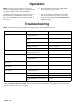
Troubleshooting guide
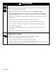
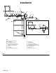
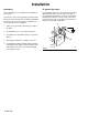
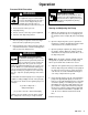

Installation
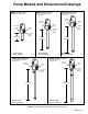
KEY
A Bleed-T
ype Master Air V
alve
B
Air Line Filter
C
Air Regulator and Gauge
D
Pump Runaway Valve (shown for
position – not needed if you use
a low level cut-of
f valve [K])
E
Air Inlet
F
Ground Wire
G
Pump (Model 204–254 shown)
H
Drain V
alve
J
Dispensing V
alve
K
Low Level Cut-Of
f V
alve
L
Male Quick Disconnect Fitting
M
Female Quick Disconnect Coupler
N
Air Line Lubricator
P
Fluid Hose
Q W
eep Hole Drain T
ube
Fig.
1
A
B
CA DE
G
F
H
K
P
J
L
M
DET
AIL A
1/2
in.
(13 mm)
Q
N
04115