
Troubleshooting guide

7
306-518
Installation
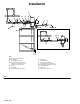
The
installation shown in Fig.1 is only a guide to se
-
lecting and installing optional and required accesso
-
ries. For assistance in designing a system to suit your
needs, contact your Graco representative or Graco
T
echnical Assistance at 1–800–543–0339.
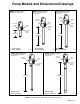
Install the pump on the drum cover so the pump’
s fluid
intake is 1/2 in. (13 mm) of
f the bottom of the drum.
On Models 204–254 and 222–087,
screw the bung
adapter tightly into the drum cover
’
s bung hole, adjust
the position of the pump in the drum, and tighten the
bung adapter screw to hold the pump.
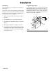
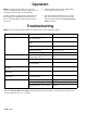
Pump Weep Hole Drain Kit
There
is a fluid weep hole (S) in the pump base. See
Fig. 2. The fluid weepage is a necessary function on all
reciprocating type pumps and should not be consid
-
ered as pump leakage. A W
eep Hole Drain Kit, Part
No. 224–907, is available to prevent the fluid from ac
-
cumulating on the exterior of the pump and surround
-
ing surfaces.
Drive the fitting (R) into the pump base weep hole (S).
Press the tube firmly onto the fitting. Route the tube
(Q) into the drum through the small hole in the cover
,
as shown in Fig.1, or route the tube into a separate
container that you have installed for that purpose.
Fig. 2
R
Q
S
04116
System Accessories
CAUTION
Do
not hang the air accessories directly on the air
inlet (E). The fittings are not strong enough to sup
-
port the accessories and may cause one or more
to break. Provide a bracket on which to mount the
accessories.
NOTE:
Install the accessories in the order shown in
Fig.1 .
1.
If you are
not
using a low level cut-of
f valve (K) at
the pump fluid intake, install a pump runaway
valve (D) to shut of
f the air to the pump if the pump
accelerates beyond the pre-adjusted setting. A
pump which runs too fast can be seriously dam
-
aged.
2.
Install an air line lubricator (N) for automatic air
motor lubrication.
3.
Next, install a bleed-type master air valve (A) to
relieve air trapped between it and the motor when
the valve is closed. Order Part No. 107–142. As an
alternative, you can install an air line quick discon
-
nect coupler (M) and fitting (L) to serve as an air-
bleed device. See Detail A in Fig.1.
T
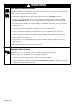
wo accessories are
required
in your system: an
air bleed device and a fluid drain valve. These ac
-
cessories help reduce the risk of serious injury in
-
cluding fluid injection, splashing in the eyes or on
the skin, and injury from moving parts if you are
adjusting or repairing the pump.
The air bleed device relieves air trapped between it
and the air motor after the air supply is shut of
f.
T
rapped air can cause the air motor to cycle unex
-
pectedly
, causing serious injury if you are adjusting
or repairing the pump. Use either a bleed-type
master air valve (A) or a quick disconnect coupler
(M) and fitting (L). Install near the pump air inlet,
within easy reach of the pump.
The fluid drain valve (H) assists in relieving fluid
pressure in the displacement pump, hoses and
dispensing valve. T
riggering the valve to relieve
pressure may not be suf
ficient.
WARNING
4.
Install the air regulator (C) to control pump speed
and pressure.
5.
Install an air line filter (B) to remove harmful dirt
and contaminants from your compressed air sup
-
ply
. Install another bleed-type master air valve (A)
to isolate the accessories for servicing.
6.
Install a drain valve (H) near the pump fluid outlet.
Order Part No. 210–658.
7.
Install a suitable fluid hose (P) and dispensing
valve (J).