
Instructions / Assembly

4
For any other assistance or information about this kit,
please call Sharp’s Customer Assistance Center at
1-800-BE-SHARP (1-800-237-4277)
SHARP ELECTRONICS CORPORATION
100 Paragon Drive, Suite #100, Montvale, New Jersey 07645
TINSEB556MRR0
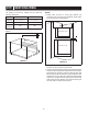
STEP 3 FRAME INSTALLATION
3. BACK FRAME INSTALLATION: Position back frame equal
space top to bottom, side to side. Mark for 4 holes, center
punch and pre-drill with 1/16" drill bit. Secure frame with
4 SCREWS (E). See Sketch 6.
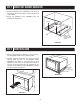
Equal gap top, bottom
Equal gap
side to side
Mounting holes
Mounting holes
Mounting holes
Mounting holes
Screw E
Screw E
Screw E
Screw E
SKETCH 6
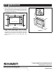
4. FRONT FRAME INSTALLATION: Place the FRONT
FRAME onto the BACK FRAME and align ball studs
and receivers. Secure the FRONT FRAME to the BACK
FRAME by rmly pushing the front frame onto the back
frame engaging the four (4) snap attachments. See
Figure 7.
Snap
Attachment
SKETCH 7