
RK94S27F, RK94S30F Installation Manual
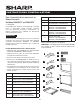

E 3
STANDARD INSTALLATION INSTRUCTIONS
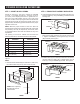
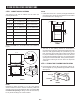
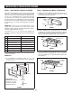
D. Position DUCT (A)-3 on top of the oven and insert it into
DUCT (A)-2. Secure DUCT (A)-3 using 3 SCREWS (I)
provided. See Figure 5.
SCREW (I)
SCREW (I)
SCREW (I)
DUCT (A)-3
DUCT (A)-2
FIGURE 5
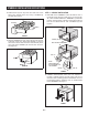
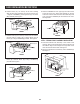
E. Remove SCREWS from the upper right and left corners
at the rear of the oven. Place duct assembly on the top
of the unit as shown and secure the duct assembly to the
oven using the 2 SCREWS just removed from the oven.
See Figure 5A.
SCREW
SCREW
FIGURE 5A
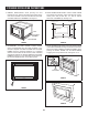
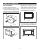
STEP 3 - SURFACE INSTALLATION
A. BOTTOM DUCT ASSEMBLY: Place the Bottom duct in
the center of the opening so that gap "A" is equal to gap
"B". When the BOTTOM DUCT ASSEMBLY is positioned
properly, the front edge of the duct will be ush with the
front of the cabinet. Secure with 2 SCREWS (H) See
Figure 6.
GAP "A"
NOTE:
CENTER BOTTOM
DUCT ASSEMBLY IN
THE OPENING
DETAIL A
GAP "B"
BOTTOM DUCT ASSEMBLY
SCREW (H)
FIGURE 6
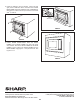
B. CABINET INSTALLATION: Place the oven adjacent to
the wall or cabinet opening. Plug the power cord into the
electrical outlet. Carefully guide the assembled oven into
the prepared opening. Slide the oven on the BOTTOM
DUCT ASSEMBLY. See Figure 7.
FIGURE 7