
RK94S27F, RK94S30F Installation Manual

E 5
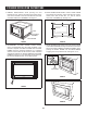
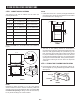
FLUSH INSTALLATION INSTRUCTIONS
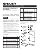
STEP 1 - CABINET OR WALL OPENING
The opening in the wall or cabinet must be within the
following dimensions:
OPENING RK94S27F RK94S30F
A 25
1
/8" (638.2 mm) 25
1
/8" (638.2 mm)
Width (B) 27
1
/8" (689 mm) 30
1
/8" (765.2 mm)
Height (C) 22
7
/16" (569.9 mm) 22
7
/16" (569.9 mm)
D 1" (25.4 mm) 2
1
/2" (63.5 mm)
E 2
1
/8" (54 mm) 2
1
/8" (54 mm)
F 1
1
/2" (38.8 mm) 1
1
/2" (38.8 mm)
G 5" (127 mm) 5" (127 mm)
Minimum
Depth (I)
20" (508 mm) 20" (508 mm)
Outlet should NOT be in the shaded area H as indicated in
Figure 1.
Mounting
cleat
F
B
A
Top View
Shelf
Cabinet
face
E
D D
Front View
Shelf
Bottom of flush cutout
H
C
B
I
G
G
FIGURE 1
NOTE:
Dimension C above will result in 1
1
⁄4" (31.8 mm) spaces
above and below the trim to allow for necessary intake and
exhaust air ow to ensure appliance does not overheat. Do
not reduce this spacing as doing so will void the warranty
for any issues resulting from a lack of airow.
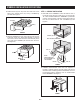
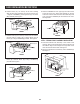
NOTE:
• Please allow minimum 3" (76 mm) wood gap between the
microwave oven cutout and the appliance cutout below
the microwave oven. See Figure 2.
3"
(76 MM)
Min.
Microwave cutout
Wall oven cutout
FIGURE 2
• The oor of the opening should be constructed of
plywood strong enough to support the weight of the oven
and oor load (approximately 100 pounds/45 kg). The
oor should be level and 90˚ with the face of the cabinet
for proper installation and operation of the oven. Be sure
to check the local building code as it may require that the
opening be enclosed with sides, ceiling and rear partition.
The proper functioning of the oven does not require the
enclosure.
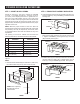
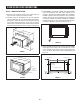
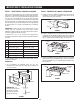
STEP 2 - EXHAUST DUCT ASSEMBLY INSTALLATION
A. Insert the edge of DUCT (B) into the hold lip of DUCT (C).
Secure together by using a SCREW (I) provided in the kit.
See Figure 3.
DUCT (C)
DUCT (B)
SCREW (I)
FIGURE 3