SJ-40J-GY/ BE SJ-W40J-GY/ BE SJ-36J-GY/ BE SJ-W36J-GY/ BE SERVICE MANUAL SX885SE39JPZL REFRIGERATOR-FREEZER MODELS SJ-40J SJ-W40J SJ-40J-GY/BE SJ-36J-GY/BE SJ-W40J-GY/BE SJ-W36J-GY/BE In the interests of user-safety (Required by safety regulations in some countries) the set should be restored to its original condition and only parts identical to those specified should be used. DESTINATION ................
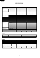
SJ-40J-GY/ BE SJ-W40J-GY/ BE SJ-36J-GY/ BE SJ-W36J-GY/ BE SPECIFICATIONS Items Type Outer dimensions (Including spacer) Height Width Depth Rated storage volume Defrosting System Start Finish Temperature control No-frost freezer Interior lamp Evaporating pan Refrigerator R tray Compartment Fresh case Vegetable case Door pocket Egg tray Bottle pocket Freezer Ice cube maker Compartment Freezer case Freezing case Deodorizing system R&L door / Dual Swing Door COLOR Items Outside color Inside color SJ-40
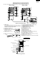
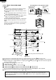
SJ-40J-GY/ BE SJ-W40J-GY/ BE SJ-36J-GY/ BE SJ-W36J-GY/ BE DESIGNATION OF VARIOUS PARTS The names in parenthesis are the denominations used in the Replacement Parts List. SJ-36J / W36J SJ-40J / W40J 9 9 11 10 1 2 3 4 5 11 1 10 10 2 3 4 5 12 6 10 12 6 10 17 7 17 7 13 14 15 8 8 16 17 Figure D-1. External Description 1. Light [Lamp] Use a 10W lamp bulb with E12 base when replacing the lamp bulb . Do use bulbs other than the specified voltage(see affixed label by the bulb) 2.
SJ-40J-GY/ BE SJ-W40J-GY/ BE SJ-36J-GY/ BE SJ-W36J-GY/ BE LIST OF ELECTRICAL PARTS ITEMS R-door switch F-Thermostat Defrost heater Damper thermostat Defrost timer TYPE NAME PS 102-S MM1-8109 — MM1-6164 TMDF704FD2 RATING 125V-1A,250V-0.5A 125V-6A,250V-3A 220-240V — 220-240V 50/ 60Hz Lamp socket Lamp Defrost thermostat Thermo.
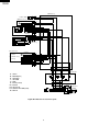
SJ-40J-GY/ BE SJ-W40J-GY/ BE SJ-36J-GY/ BE SJ-W36J-GY/ BE WIRING DIAGRAM Be sure to replace the electrical parts with specified ones for maintaining the safety and performance of the set. G : GRAY Br : BROWN(live) YG : YELLOWISHGREEN Y YELLOW R : RED P : PINK B : BLUE(neutral) Bk : BLACK S-B : SKY-BLUE G-Y : GREEN-YELLOW(earth) W : WHITE O : ORANGE CONNECTED IN TERMINAL BOX CONNECTOR (O) C-thermostat V-heater Defrost timer F-thermostat (BR) (R) (G) TM Lamp Thermo.
SJ-40J-GY/ BE SJ-W40J-GY/ BE SJ-36J-GY/ BE SJ-W36J-GY/ BE Cabinet ass'y R-door switch 1 2 1 2 B-1 1 2 1 2 (S-B-1) 1 2 3 4 5 6 1 2 3 4 5 6 R-1 1 2 3 4 1 2 3 4 Multi-louver ass'y Lamp Socket ass'y TM Defrost timer 1 4 2 3 1 4 2 3 L D timer lead ass'y RC box ass'y V heater S-B-1 Br-1 Bk-1 G-1 Y-1 Y-2 G-3 O-1 (R-1) Br-2 Lead wire FC-box ass'y F-thermostat C-partition ass'y EV-cover ass'y Lead wire EV-cover ass'y Fan motor FM Def. thermo. ass'y Fuse ass'y Def.
SJ-40J-GY/ BE SJ-W40J-GY/ BE SJ-36J-GY/ BE SJ-W36J-GY/ BE FUNCTIONS 1. ADJUSTABLE TEMPERATURE CONTROL (1) Temperature control of freezer Thermostat (senses freezer temperature) operates on ON/OFF switchover to control the compressor and allows the freezer temperature to keep at a suitable temperature. However adjust the freezer temp. control knob as follows depending upon the storing condition of foods. FREEZER TEMP.
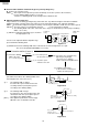
SJ-40J-GY/ BE SJ-W40J-GY/ BE SJ-36J-GY/ BE SJ-W36J-GY/ BE The explanation of the operation manual 2. R & L DOOR / DUAL SWING DOOR (1). Structure Note Do not destroy or damage the refrigerator body's structure or internal structure intentionally. Do not put any objects on the lower hinge or lower hinge pin. Please pay attention to the lower hinge pin and the cam, do not let them get stuck.
SJ-40J-GY/ BE SJ-W40J-GY/ BE SJ-36J-GY/ BE SJ-W36J-GY/ BE (2) Disassembly, assembly and adjustment of R & L door 1 List of parts concerned with R & L door Top hinge cover Door cam tr Special screw Hinge cam tl Door cam tl Top hinge ass'y Table support Hinge cam tr Silicon grease (Before replacing door, also prepare silicon grease.
SJ-40J-GY/ BE SJ-W40J-GY/ BE SJ-36J-GY/ BE SJ-W36J-GY/ BE 3Removal and installation of Bottom hinge ass'y and Top hinge ass'y Remove the relevant screws. NOTE After replacement, adjust the position relationship of the door. (Refer to the next item.) Proper climbing width of roller: 1 to 1.5 mm Tolerance of climbing width of left and right rollers: within 0.
SJ-40J-GY/ BE SJ-W40J-GY/ BE SJ-36J-GY/ BE SJ-W36J-GY/ BE (4) Check the balance of the door opening force, selfclosing force and roller climbing width between the left and right sides. • Referring to the right figure, check the climbing width. R & L door Door cam bottom Lower hinge ass'y When the balance is poor between the left and right sides, proceed with the following work. 0.5 to 1 mm (both left and right sides) Hinge pin Figure F-13 (5) Adjust the upper hinge.
SJ-40J-GY/ BE SJ-W40J-GY/ BE SJ-36J-GY/ BE SJ-W36J-GY/ BE 3. DEFROSTING (2) Where is melted ice brought (1) No defrosting operation is necessary 1. Melted ice is brought into the evaporating pan No defrosting operation is necessary. at the back of the set and is evaporated here As this machine is so designed that a built-in by the heat of compressor. evaporator cools air and a fan circulates cooled 2.
SJ-40J-GY/ BE SJ-W40J-GY/ BE SJ-36J-GY/ BE SJ-W36J-GY/ BE (4) As a reference to determine the causes of trouble, malfunction and phenomena are described below. Refer to the following when repairing. 1. Disconnection of defrost heater As off-cycle defrosting is performed, the defrosting time is extremely prolonged. Each time defrosting is started, the freezer temperature rises and a portion of ice and stored foods are melted. 2. Melted thermo. fuse or opened-circuit due to the defect of defrost thermostat.
SJ-40J-GY/ BE SJ-W40J-GY/ BE SJ-36J-GY/ BE SJ-W36J-GY/ BE ASSEMBLING PROCEDURES OF MAIN PARTS AND CAUTIONS 1.C-INSULATION ASSEMBLY(A340) Corner sealer l V-heater C-partition r F-thermo.capi. tube Drain sealer a F-thermostat Center insulation a A sealer rf b W-sealer fr a C-partition f Lead wire f-box Corner sealer r W-sealer rf-c A-sealer ag5 A sealer rf c Figure A-1 1. Stick A-sealer rf c on outside of C-partition f. C-partition f A sealer rf c Figure A-2 2. Insert F-thermo capi.
SJ-40J-GY/ BE SJ-W40J-GY/ BE SJ-36J-GY/ BE SJ-W36J-GY/ BE 4. Form capillary tube of F-thermostat as shown Figure A-3, hook each side the claw of C-partition f. (Figure A-4) Corner sealer r Corner sealer l 5. Form the end of capillary tube of F-thermostat and fix with claw as shown. (Figure A-4 or Figure A-5) A sealer rf c Tapping screw C-partition f B F-thermostat Figure A-4 6. Stick W-sealer rf c . (Figure A-5 ) F-thermo capi. tube Lead wire f box W-sealer rf c Figure A-5 5mm 7.
SJ-40J-GY/ BE SJ-W40J-GY/ BE SJ-36J-GY/ BE SJ-W36J-GY/ BE 2.RC-BOX COV. ASSEMBLY (A195) Thermo. cap.sealer Dial sealer Defrost timer Damper thermostat A sealer ag 2 A sealer ag 3 R control label A sealer ag 4 R-air guider R-temp. control knob A-sealer ag 1 R-c box cover D timer lead ass'y Figure A-8 1. Stick sealers as show figure.
SJ-40J-GY/ BE SJ-W40J-GY/ BE SJ-36J-GY/ BE SJ-W36J-GY/ BE Defrost timer 2. Connect D timer lead ass’y to defrost timer. D timer lead ass'y Figure A-10 3. Fix defrost timer on R-c box cover with tapping screw. R-c box cover Defrost timer Tapping screw Figure A-11 4. Fasten damper thermostat on foodliner with 2 tapping screws. Tapping screw Tapping screw Figure A-12 5. Fix “1” ass’y on “4” ass’y. Figure A-13 6. Fasten R-c box cover on “5” ass’y with 3 tapping screws.
SJ-40J-GY/ BE SJ-W40J-GY/ BE SJ-36J-GY/ BE SJ-W36J-GY/ BE 3. E.V. COVER ASSEMBLY (A800) E. v.cover B B E.v.cover sealer d Fuse ass'y Figure A-15 E.v.cover sealer c Tapping screw Fan motor ass'y L band c E.v. cover sealer b L band c Defrost thermo ass'y Don't loosen Set metal side below Al Tape E.v cover insulation E.v.cover sealer a Fuse ass'y E.v.water sealer E.v.
SJ-40J-GY/ BE SJ-W40J-GY/ BE SJ-36J-GY/ BE SJ-W36J-GY/ BE 1. Stick U sealer handle to Fan motor holder a. C Fan motor holder a 4. Set Fan clamp to Propeller fan and insert it to the shaft of Fan motor. Propeller fan 100 Fan clamp _ 7+2mm Motor cushion Fan clamp Motor cushion Fan boss SEC. C-C C right wrong Figure A-17 Figure A-20 2. Insert the terminals of Lead e.v. cover ass’y to Fan motor. 5. Fix L band c. Installation of L band c Not come out of claw 10±5mm Fan motor SEC.
SJ-40J-GY/ BE SJ-W40J-GY/ BE SJ-36J-GY/ BE SJ-W36J-GY/ BE 4. MULTI LOUVER ASSEMBLY (A165) A-sealer m-louver a Multi louver ins. Multi louver Lamp label Lamp socket W sealer r-air-g Lamp Lamp cover Figure A-23 1. Stick A sealer m-louver a on Multi louver ins. Multi louver ins. A sealer M-louver A A sealer M-louver A 3. Screw Lamp into Lamp socket. 4. Fix Lamp socket on Multi louver ins. on Multi louver with tapping screw. 5. Set multi louver ins. on Multi louver. (match each hole) 6.
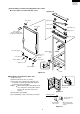
SJ-40J-GY/ BE SJ-W40J-GY/ BE SJ-36J-GY/ BE SJ-W36J-GY/ BE COOLING UNIT Mark: Refrigerant flow Mark: Brazing portion Inner condenser C L R Back condenser Evaporator Suction pipe Bottom condenser Compressor Capillary tube Dryer Figure C-1. Cooling unit Bottom condenser to Hot pipe Capillary tube Pinch Point S.
SJ-40J-GY/ BE SJ-W40J-GY/ BE SJ-36J-GY/ BE SJ-W36J-GY/ BE REPLACEMENT PARTS LIST (SJ-W40J / W36J) REF. NO. PART NO.
SJ-40J-GY/ BE SJ-W40J-GY/ BE SJ-36J-GY/ BE SJ-W36J-GY/ BE REF. NO. PART NO.
SJ-40J-GY/ BE SJ-W40J-GY/ BE SJ-36J-GY/ BE SJ-W36J-GY/ BE REF. NO. PART NO. DESCRIPTION Q'TY CODE SJ-W40J SJ-W40J SJ-W36J SJ-W36J -GY -BE -GY -BE OTHER PARTS 4-21 4-22 4-23 4-24 4-140 4-141 4-142 LX-TZA046CBE0 LX-TZ0127CBE0 LX-TZA042CBE0 LX-DZ0133CBE0 LX-BZA018CBE0 QTAN-A013CBE0 QTAN-A012CBE0 Special screw Special screw Special screw Special screw Special screw Solderless term. a Solderless term.
SJ-40J-GY/ BE SJ-W40J-GY/ BE SJ-36J-GY/ BE SJ-W36J-GY/ BE REPLACEMENT PARTS LIST (SJ-40J / 36J) REF. NO. PART NO.
SJ-40J-GY/ BE SJ-W40J-GY/ BE SJ-36J-GY/ BE SJ-W36J-GY/ BE REF. NO. PART NO.
SJ-40J-GY/ BE SJ-W40J-GY/ BE SJ-36J-GY/ BE SJ-W36J-GY/ BE REF. NO. PART NO.
SJ-40J-GY/ BE SJ-W40J-GY/ BE SJ-36J-GY/ BE SJ-W36J-GY/ BE 1 2 3 4 5 6 DOOR PARTS A A 3-26-1 3-27 SJ-40J/36J 3-26-1 3-26-2 SJ-W40J/W36J 3-26 B 5-118 B 3-33 3-31 3-32 C 5-121 3-29 4-22 5-117 C 3-29 4-22 3-30 3-28 3-26-7 3-26-5 3-26-8 SJ-W40J/W36J 3-26-4 D 5-118 3-26-5 3-26-6 D SJ-W40J/W36J 3-30 3-28 SJ-40J/36J 4-21 3-26-7 3-26-3 SJ-W40J/W36J 3-26-9 3-26-5 SJ-40J/36J 5-115 5-115-2 E E 5-115-1 F F 3-23 5-124 G G 3-22 3-21 H H 1 2 3 4 28 5 6
SJ-40J-GY/ BE SJ-W40J-GY/ BE SJ-36J-GY/ BE SJ-W36J-GY/ BE 1 2 3 4 5 6 CABINET PARTS A A 5-119 5-120 B B 5-122 5-125 2-28 SJ-W40J/W36J 5-116 2-28 4-24 SJ-40J/36J 5-114 C C 5-112 2-22 2-21 SJ-W40J/W36J 5-113 5-123 4-23 2-21 SJ-40J/36J 2-23 2-29 D D 1-89 2-92 2-94 2-107 2-96 2-70 1-51 2-91 2-112 E E 2-71 2-97 2-104 2-93 2-30 2-106 2-101 2-56 F 2-67 2-105 F 2-73 2-98 2-72 2-5 1-87 4-141 2-4 2-95 G 2-72 2-57 1-86 2-2-1 G 2-64 2-2 5-111 2-2-1 1-88 4-14
SJ-40J-GY/ BE SJ-W40J-GY/ BE SJ-36J-GY/ BE SJ-W36J-GY/ BE 1 2 3 4 5 6 CABINET PARTS A A 2-60 2-59 2-58 B B 2-88 2-86 2-85 C C 2-111 1-83 2-103 1-84 2-84 D D 2-52 6-53 2-54 2-81 6-52 2-68 2-55 2-75 1-82 2-82 2-87 2-53 E 2-90 E 1-85 2-74 2-51 2-89 1-81 2-147 F 2-145 2-142 2-145 2-141 1-142 F 2-150 2-148 2-143 1-140 2-151 G 2-140 2-144 2-149 2-61 1-143 G 2-147 2-152 2-63 2-153 H 2-146 1-141 2-66 2-154 H 2-62 1 2 3 4 30 5 6
SJ-40J-GY/ BE SJ-W40J-GY/ BE SJ-36J-GY/ BE SJ-W36J-GY/ BE 1 2 3 4 5 6 CYCLE PARTS A A 6-154 B B 6-153 6-148 6-152 C C 6-149 6-151 6-51 6-141 D D 2-69 6-143 1-148 4-140 2-65 E E 1-144 6-144 6-140 1-145 6-142 F F 6-146 6-147 G G H H 1 2 3 4 31 5 6
SJ-40J-GY/ BE SJ-W40J-GY/ BE SJ-36J-GY/ BE SJ-W36J-GY/ BE 39JPYL / 39JPZL / 39JPRL / 39JPBL / 35JPYL / 35JPZL / 35JPRL / 35JPBL 32 '98 SHARP CORP. (11U0.