
Service manual


SJ-40J-GY/ BE
SJ-W40J-GY/ BE
SJ-36J-GY/ BE
SJ-W36J-GY/ BE
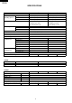
5
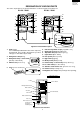
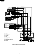
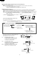
WIRING DIAGRAM
Be sure to replace the electrical parts with specified ones for maintaining the safety and performance of the set.
Figure W-1. Wiring Diagram
F-thermostat
C-thermostat
(R)
Defrost timer
TM
Thermo.fuse
Protector
Compressor
C
A
M
Starting relay
FM
Fan motor
(O)
Door
switch
(B)
Defrost thermostat
Defrost heater
(W)
(BK)
(Y)
Lamp
(S-B)
(G)
(BR)
Terminal block
Source cord
E
G
Br
YG
Y
R
P
B
Bk
S-B
G-Y
W
O
: GRAY
: BROWN(live)
: YELLOWISHGREEN
YELLOW
: RED
: PINK
: BLUE(neutral)
: BLACK
: SKY-BLUE
: GREEN-YELLOW(earth)
: WHITE
: ORANGE
CONNECTOR
CONNECTED IN TERMINAL BOX
L
(O)
V-heater