
Service manual


SJ-40J-GY/ BE
SJ-W40J-GY/ BE
SJ-36J-GY/ BE
SJ-W36J-GY/ BE
9
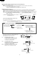
(2) Disassembly, assembly and adjustment of R & L door
11
11
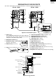
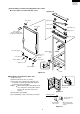
1List of parts concerned with R & L door
Figure F-8
Figure F-6
22
22
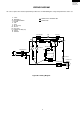
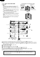
2Installation and removal of R & L door
(1) Open the door.
(2) Remove the door cam. (3 screws)
(3) Close the door, and open its opposite side.
In this time, hold the door with both hands to
prevent the door from falling.
NOTE When replacing the door with the new
one, coat grease on the slide surface.
(Grease all door arms on the four
corners.)
(4) Pull off the door upward.
(5) For installation, reverse the above procedure.
Figure F-7
The door cam tr is
shown here.
Greasing surface
All around the
side surface
All around the side
surface, and bottom
surface
The door cam tr is
shown here.
Top hinge ass'y
Hinge cam tr
Hinge cam tl
Table support
Special screw
Door cam tl
Door cam tr
Silicon grease
(Before replacing door,
also prepare silicon grease.)
Door cam support
Door cam
support
Roller r ass'y
Door cam bl
R-door stopper l
Roller l ass'y
R-door stopper l
Door cam br
Body
Screw
Bottom hinge
ass'y
Top hinge coverTop hinge cover
Special screw
Hinge projection
Hinge pin