
Installation Instructions

E 2
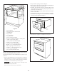
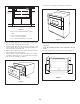
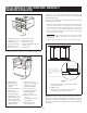
1. Prepare cabinet opening as shown in Figure 2.
2. Place the drawer adjacent to the wall or cabinet opening. Plug the
power supply cord into the electrical outlet.
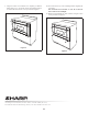
3. Carefully guide the drawer into the prepared opening. Avoid
contact with the sides of the cutout opening and pinching the cord
between the oven and the wall.
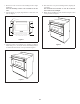
4. Slidethedrawerallthewaybackuntilthesiderailsareushwith
the face of the cabinet.
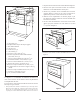
5. Open the drawer. Using the 4 holes on the drawer as a template,
pre-drill the cabinet using a
1
/16" (1.6 mm) bit. Secure the drawer
with the 4 screws supplied. See Figure 3.
Side
Rail
Figure 3
6. Close drawer to complete oven installation. See Figure 4.
Figure 4
B
C
D
E
F
G
H
I
I
O
J
K
L
Q
M
N
P
A
O
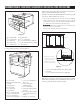
Figure 2
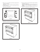
A. 6" (152.40 mm)
B. Suggested electrical outlet location*
C. Anti-Tip block
D. 5" (127 mm)
E. 3
1
/2" (88.90 mm)
F. 4" (101.60 mm)
G. 22
1
/8" (561.98 mm) opening
H. 14
13
/16" (376.24 mm) to bottom of Anti-Tip block
I. Allow
7
/8" (22.22 mm) overlap
J. 23
1
/2" (596.90 mm) minimum depth
K. Allow
7
/16" (11.11 mm) overlap
L. 36" (914.40 mm) countertop height
M. Allow
7
/16" (11.11 mm) minimum space
N. Floor must support 100 lb (45.4 kg)
O. Allow 4
1
/8" (104.4 mm) minimum space
P. 15
9
/16" (395.3 mm) opening
Q. 30" (762.0 mm) minimum width
Figures 1 and 2 contain many Microwave Drawer measurements for
reference when planning the drawer’s location.
This Microwave Drawer can be installed below any electric or gas
wall oven.
* Can also be installed using an electrical outlet in an adjacent
cabinet within the area where the provided electrical cord can
reach. Power cord access hole in cabinet should be a minimum
1
1
/2" diameter hole and deburred of all sharp edges.
IMP O R TANT
Always allow sufcient power cord length to the
electrical outlet to prevent tension.
Always check electrical codes for requirements.