
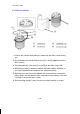
Specifications
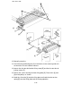
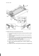
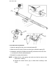
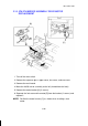

17. Attach blue wires [1 and 3] around the pulleys as shown.
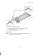
18. Attach wire [3] to the wire fixing plate [A], then hook one end of tension
spring [B] to the fixing plate and the other end to the frame projection.
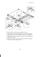
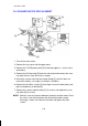
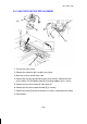
19. Tighten the first scanner clamps [C] and remove the four positioning pins
and the omega clamp.
20. Perform free run (turn DIP switch 101-1 ON) for 10 minutes and make
sure that the scanners operate smoothly.
3
6-1
2/5
1
6-2
[C]
4
[3]
[B]
[A]
[1]
[C]
[3]
[1]
1 December 1990
5-18