
Specifications
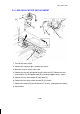
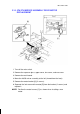

2.8 SCANNER MOTOR REPLACEMENT
1. Turn off the main switch.
2. Remove the rear cover and the upper cover.
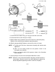
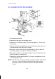
3. Remove the CC/G/B power pack [A] (2 locking supports, 1 screw, and 4
connectors).
4. Remove the 6P connector [B] from the main board and remove the scan-
ner motor harness from the harness clamps.
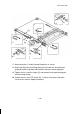
5. Secure the scanner wire with the omega clamp [C] so that it does not
come off the pulley. (Use tape if no clamp is available.)
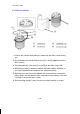
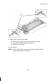
6. Remove the two Allen screws [D] securing the scanner motor pulley and
place it temporarily on bracket [E].
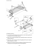
7. Remove the scanner motor bracket [F] (3 screws) and replace the scan-
ner motor [G] (2 screws).
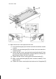
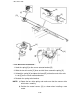
NOTE: Maintain 1mm of clearance between the pulley and the motor. Place
the scale (1 mm thick) between the drive pulley and the motor
bushing as shown in the above illustration and tighten the Allen
screws.
[B]
[F]
[G]
[A]
[D]
[C]
[E]
1mm
1 December 1990
5-21