VC-A565U/H965U SUPPLEMENT SERVICE MANUAL S62K8VC-A565U SUPPLEMENT VIDEO CASSETTE RECORDER VC-A565U MODELS VC-H965U VC-A565U VC-H965U In the interests of user-safety (Required by safety regulations in some countries) the set should be restored to its original condition and only parts identical to those specified be used. OUTLINE This Supplement describes corrections of the mechanism in the VC-A565U/H965U Service Manual already issued.
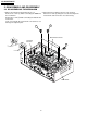
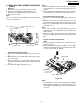
VC-A565U/H965U SUPPLEMENT 2. DISASSEMBLY AND REASSEMBLY 2-2 DISASSEMBLING THE MECHANISM 2. Removing the mechanism and cassette housing. 1. When removing the mechanism from the set. Remove 2 screws 3 fixing the cassette housing to the Remove the screw 2 which connecting the PWB and mechanism, and remove the cassette housing. the mechanism. Remove the screw 4 which connecting mechanism and main frame. Take out vertically the mechanism so that it does not damage the adjacent parts.
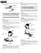
VC-A565U/H965U SUPPLEMENT 2-3 CARES WHEN REASSEMBLING Rotate the flange of worm gear by using thin stick. CW • • • Loading direction CCW • • • Ejection direction Note Be careful not to damage the gear of worm gear and worm wheel gear. It might cause a strange sound. INSTALLING THE CASSETTE HOUSING When the cassette housing is installed on the mechanism, the initial setting is essential condition. There are two initial setting methods, namely electrical and mechanical. 1.
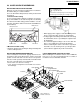
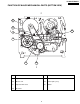
VC-A565U/H965U SUPPLEMENT 3. FUNCTION OF MAJOR MECHANICAL PARTS (TOP VIEW) 17 15 18 26 10 16 14 1 9 2 11 3 5 7 8 6 No. 4 12 Function 13 No.
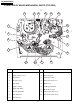
VC-A565U/H965U SUPPLEMENT FUNCTION OF MAJOR MECHANICAL PARTS (BOTTOM VIEW) 21 22 25 19 20 23 No. 24 Function No. Function 19 Syncro Gear 23 Clutch lever 20 Master cam 24 Limiter pulley ass’y 21 Capstan D.D.
VC-A565U/H965U SUPPLEMENT 4. ADJUSTMENT, REPLACEMENT AND ASSEMBLY OF MECHANICAL UNITS The explanation given below relates to the on-site general service (field service) but it does not relates to the adjustment and replacement which need high-grade equipment, jigs and skill. For example, the drum assembling, replacement and adjustment service must be performed by the person who have finished the technical courses.
VC-A565U/H965U SUPPLEMENT 4-2 MAINTENANCE CHECK ITEMS AND EXECUTION TIME Perform the maintenance with the regular intervals as follows so as to maintain the quality of machine. Maintained 500 1000 1500 2000 Possible symptom Remarks encountered hrs. hrs. hrs. hrs. Parts Abnormal rotation or significant Guide roller ass’y vibration requires replacement. Sup guide shaft Reverse guide Lateral noises Head occasionally blocked Clean tape contact part with the specified cleaning liquid.
VC-A565U/H965U SUPPLEMENT 4-3 REMOVING AND INSTALLING THE CASSETTE HOUSING 2. Install in the reverse order of removal. • Removal 1. In the cassette removing mode, remove the cassette. 2. Unplug the power cord. 3. Remove in the following numerical order. a) Remove two screws 1. b) Pull and circle the drive lever and pull up the cassette housing control. Notes 1. In the case when you use the magnet screw driver, never approach the magnet driver to the A/C head, FE head, and drum. 2.
VC-A565U/H965U SUPPLEMENT 4-5 REEL DISK REPLACEMENT AND HEIGHT CHECK • Removal 1. Remove the cassette housing control assembly. 2. Remove the Supply/Take-up main brake ass'y. 3. Remove tension band from the tension arm ass'y. 4. Remove the reel disk. Note: Take care so that the tension band ass'y and main brake ass'y are not deformed. Tension Take-up main brake ass'y Ten arm ass'y Supply main brake Tension band ass'y Supply reel disk Take-up reel disk Notes: 1.
VC-A565U/H965U SUPPLEMENT Note: Whenever replacing the reel disk, perform the height checking and adjustment. Reel disk height adjusting jig Master plane 10 ± 0.2mm 4-7 CHECKING AND ADJUSTMENT OF TAKEUP TORQUE IN REWIND MODE Mechanism chassis Reel disk Notes: 1. Hold the torque gauge by hand so that it is not moved. 2. Do not keep the reel disk in lock state. Do not allow longtime measurement. • Remove the cassette housing control assembly.
VC-A565U/H965U SUPPLEMENT Notes: 1. Hold the torque gauge by hand so that it is not moved. 2. Do not keep the reel disk in lock state. Do not allow longtime measurement. 4-9 CHECKING AND ADJUSTMENT OF TAKEUP TORQUE IN VIDEO SEARCH REWIND MODE 4-8 CHECKING AND ADJUSTMENT OF TAKEUP TORQUE IN RECORD/PLAYBACK MODE • After short-circuiting between TP803 and TP802 provided at operation PWB, plug in the power cord. • Remove the cassette housing control assembly.
VC-A565U/H965U SUPPLEMENT 4-10 CHECKING THE VIDEO SEARCH REWIND BACK TENSION • Remove the cassette housing control assembly. • After short-circuiting between TP803 and TP802 provided at main PWB, plug in the power cord. Tension gauge 900 - 1,200gf Pinch roller • Checking 1. After pressing the play button, press the rewind button, and set the video search rewind mode. 2.
VC-A565U/H965U W CC CW • Checking 1. Set a cassette tape, push the REC button to place the unit in the SP record mode. Now check the tension pole position. 2. Visually check to see if the position of the tension pole is within the 0 +0.5 –0.2 mm from the left side line. SUPPLEMENT Tension pole adjustment driver adjusting direction Standard A = 0 + 0.5 mm - 0.2 Tension pole adjustment driver Figure 4-16. A Make the adjustment with the beginning of a T-120 tape. Figure 4-13.
VC-A565U/H965U SUPPLEMENT • Adjustment 1. If the indication of torque cassette meter is lower than the setting, shift the tension spring engagement to the part A. 2. If the indication of torque cassette meter is higher than the setting, shift the tension spring engagement to the part B. A • Checking the brake torque at the take-up side Torque gauge Tension arm B CW CCW Take-up reel disk Tension spring CCW: 4.41 ± +2.0 –1.5 mN⋅m (45 ± CW: 4.12 ± +1.5 –1.2 mN⋅m (42 ± Figure 4-18.
VC-A565U/H965U SUPPLEMENT 3. Align the left end of gear of A/C head arm with the punched mark of chassis, tentatively tighten the screws 1 so as to ensure smooth motion of A/C head arm. Tightening torque must be 0.45 ± 0.05N·m (4.5 ± 0.5kgf·cm). 4-15 REPLACEMENT OF A/C (AUDIO/CONTROL) HEAD 1. In eject position unplug the power cord. • Removal 1. Take out FFC holder from main chassis. AC Head FFC (Push 3 hooking point and pull-up the Holder holder). 2. Remove the screws 123, Tilt screw. 3.
VC-A565U/H965U SUPPLEMENT 4-16 A/C HEAD HEIGHT ROUGH ADJUSTMENT 4-17 ADJUSTMENT OF TAPE DRIVE TRAIN 1. Tape run rough adjustment 1 Check and adjust the position of the tension pole. (See 4-12.) 2 Check and adjust the video search rewind back tension. (See 4-10.) 3 Connect the oscilloscope to the test point for PB ATR signal output (TP201). Set the synchronism of the oscilloscope to EXT. The PB ATR signal is to be triggered by the head switching pulse (TP202). 4 Set the alignment tape (VROATSV) to play.
VC-A565U/H965U SUPPLEMENT Notes: 1. Previously set the tracking control in the center position, and adjust the ATR signal waveform to maximum with X value adjustment nut. Thereby the tape run rough adjustment is facilitated. 2. Especially the outlet side ATR signal waveform must have higher flatness. Figure 4-27. 2. Adjustment of A/C head height and azimuth 1 Perform the initial setting of A/C head position by the method stated in "4-15 Replacement 3".
VC-A565U/H965U SUPPLEMENT 3 Next, press the tracking button (+), (–) and change the ATR signal waveform from max to min and from min to max. At this time adjust the height of supply and take-up side guide roller with the adjustment driver (JiGDRiVERH-4) so that the ATR signal waveform changes nearly parallel. 4 If the tape is lifted or sunk from the helical lead surface, the PB ATR signal waveform appears as shown in Figure 4-30.
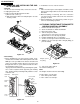
VC-A565U/H965U SUPPLEMENT 4-18 REPLACEMENT OF THE CAPSTAN D.D. (DIRECT DRIVE) MOTOR • Remove the mechanism from the set. • 1. 2. 3. Removal (Follow the order of indicated numbers.) Unsolder loading motor wire and drum FFC. Remove the reel belt 1. Remove the three screws 2. 2 Main chassis Solder loading motor wire Capstan D.D. motor Solder drum FFC 4-19 REPLACEMENT OF DRUM D.D. MOTOR 1. Set the ejection mode. 2. Withdraw the main power plug from the socket. • 1. 2. 3. 4. 5.
VC-A565U/H965U SUPPLEMENT 4-20 REPLACING THE UPPER AND LOWER DRUM ASSEMBLY 4-21 ASSEMBLING OF PHASE MATCHING MECHANISM COMPONENTS • Replacement (Perform in the numerical order) 1 Remove the motor as stated in 4-19 D.D. motor replacement. 2 Remove the drum earth brush ass’y 2. 3 Remove the upper and lower drum assembly from main chassis 1. 4 Remove the drum FFC holder 3. • Assemble the phase matching mechanism components in the following order. 1. Assemble the reverse guide lever and pinch drive cam. 2.
VC-A565U/H965U SUPPLEMENT 1. Make sure that the loading arm T and S are at the PhaseMatching point as shown below a . 2. Fix the shifter position setting part to the roading arm T position setting part as shown in figure .b 3. Make sure tension arm not run on the shifter as shown in figure c . 4-22 INSTALLING THE SHIFTER Drum Capstan D.D. motor (Bottom side of mechanism chassis) Figure 4-36.
VC-A565U/H965U SUPPLEMENT 4-23 INSTALLING THE MASTER CAM (AT REAR SIDE OF MECHANISM CHASSIS) 4-24 REPLACEMENT OF LOADING MOTOR • Removal 1. Make sure beforehand that the shifter is at initial position. (Right side from bottom view) 2. Place the master cam in the position as shown below. 3. Fix the E ring. E-ring Apply grease *Apply grease to the tip as well. Worm gear Apply grease Loading motor. Leading connect gear. Apply grease Worm wheel gear.
VC-A565U/H965U SUPPLEMENT 4-25 ASSEMBLY OF CASSETTE HOUSING 1. Proof lever Proof lever spring and Holder R MSPRD0215AJFJ *Proof lever spring fixing direction designated. Figure 4-41. 2. Open lever, Sensor Plate and Drive Lever to Frame R Outer Top Outside Inner Bottom Take care not to damage this part 3.
VC-A565U/H965U SUPPLEMENT 4. Frame R, Frame L, Drive Arm R, Drive Arm L, Upper Plate. LANGF9661AJFW Top surface should be free from scratches or soil. When assemble drive lever to frame R, make sure the hole synchronize.
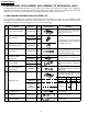
S Sensor Close Open 0 0 0 0 1 1 0 SLOW FF STOP 1 1 PU2 VSR 1 1 1 0 0 0 0 0 1 1 ULD PB 1 1 0 1 0 1 PU2 PU2 180 PU Code 2 1 PU1 0 0 1 1 Code 1 0 1 1 CS/EJ 1 1 or 0 1 120 PU1 Mecha Mode 0 0 1 1 1 1 Code 1 S Sensor Code 2 0 UL 0 1 1 0 0 60 UL 0 CS/EJ EJ Code 2 Code 1 Mode check Cam mark Mecha Mode H Mechanical Timing 0 0 240 PB 0 0 0 0 1 1 0 1 VSR VSR 0 0 0 0 PB 0 1 SLW STILL SLOW 0 1 0 0 300 0 0 1 1 FF REW F
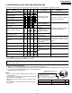
REC/PLAY 26 VSF End Set capstan motor to search speed. Press FF key. PLAY Unloading End YES Is take-up reel sensor signal outputted ? Picture appears. Capstan motor turns counterclockwise. Press REC/PLAY key. STOP NO Slow brake pressing STILL STOP End Stop capstan motor. Capstan motor turns in reverse direction. Press STOP key. REC/PLAY End Capstan motor stops. Loading motor stops. Mode switch is at STILL position. Slow brake comes into contact with capstan motor.
Brake function FF/REW operation FF/REW STOP 27 End Loading Motor stop rotate. Mode SW at PB position. Loading motor reverse direction. Loading motor stops. Mode switch is at Stop position. Stop capstan motor. Loading motor turns forward direction. Press STOP key. FF/REW End Turn capstan motor in normal or reverse direction, after the remaining tape has been detected. Loading Motor stop rotate. Mode SW is at FF/REW position. Loading motor rotate forward. Press FF/REW key.
NO 28 The cassette tape is presumably damaged. YES Is the pulse NO outputted from reel sensor ? YES Are idler wheel NO ass’y and reel disk in mesh ? YES Does capstan NO motor turn in FF (or REW) direction ? YES Is master cam at FF position ? Replace the reel sensor. Replace the idler ass’y. Replace the capstan motor. YES Are Vco 23V and Vcc 5V applied ? Loading motor control system in trouble.
NO NO 29 Check main PWB. YES Is pulse outputted NO from reel sensor ? YES Is supply reel disk NO winding torque normal ? YES Are idler wheel NO ass’y and supply reel disk in mesh ? YES Master cam shifting to VSR position ? Press REW key. YES Is Playback function normal ? Replace reel sensor. Replace limiter pulley ass’y. Replace idler gear ass’y. Go to 2. REC/ PLAY FAILURE routine. Go to 2. REC/ PLAY FAILURE routine. 3. WINDING FAILURE AT VSR Replace loading motor block.
Check drive system’s gears for damage. Replace damaged gear with new one. • Reel disk • Limiter pulley ass’y • Idler gear ass’y NO Turn capstan motor by hand. Unusual sound heard ? NO Drive system out of contact with any part on main PWB ? YES Thrust gap found at reel disk ? YES Is reel disk height as specified ? 4-ii) Unusual sound in FF/REW mode YES YES NO NO Replace capstan motor. Rearrange the parts on main PWB. Check reel disk and main chassis. And replace defective parts.
VC-A565U/H965U SUPPLEMENT 31
VC-A565U/H965U SUPPLEMENT COPYRIGHT © 2002 BY SHARP CORPORATION ALL RIGHTS RESERVED. No part of this publication may be reproduced, stored in a retrieval system, or transmitted in any form or by any means, electronic, mechanical, photocopying, recording, or otherwise, without prior written permission of the publisher. SHARP CORPORATION AV Systems Group Quality & Reliability Control Center Yaita, Tochigi 329-2193, Japan D SEM P SMM TQ1283-S Mar. 2002 Printed in JAPAN NA.