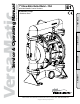
with Non-Metallic Center Sections E1 3: EXP VIEW 2: INSTAL & OP 1: PUMP SPECS E1 Metallic Pumps • Stainless Steel 4: WARRANTY Service & Operating Manual Original Instructions Versa-Matic 1" Elima-Matic Bolted Metal – FDA VERSA-MATIC® • Warren Rupp, Inc. • A Unit of IDEX Corporation 800 North Main Street, Mansfield, OH 44902 USA • Phone: (419) 526-7296 • www.versamatic.com © Copyright 2012 Warren Rupp, Inc.
Safety Information IMPORTANT WARNING Read the safety warnings and instructions in this manual before pump installation and start-up. Failure to comply with the recommendations stated in this manual could damage the pump and void factory warranty. When the pump is used for materials that tend to settle out or solidify, the pump should be flushed after each use to prevent damage. In freezing temperatures the pump should be completely drained between uses.
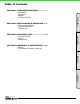
SECTION 2: Installation & Operation.......5 • Principle of Pump Operation • Typical Installation Guide • Troubleshooting SECTION 3: Exploded View............................8 • Composite Drawings • Parts List • Materials Code 4: WARRANTY 3: EXP VIEW SECTION 4: Warranty & Certificates.....10 • Warranty • CE Declaration of Conformity - Machinery 2: INSTAL & OP SECTION 1: Pump Specifications.................
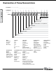
Explanation of Pump Nomenclature Your Serial #: (fill in from pump nameplate)______________________________________ 1: PUMP SPECS Your Model #: (fill in from pump nameplate) Model #: __ __ __ __ __ __ __ __ __ __ __ __ VERSA-MATIC® MODEL IDENTIFICATION CODES __ X X X X X X X X X X - X X X Options (if applicable) Revision Level Construction Design Valve Seat Material/Valve Seat O-ring Material Valve Ball Material Diaphragm Series Diaphragm Material Non-Wetted Parts Wetted Parts Pump Size Mo
Material Profile: Operating Temperatures: CAUTION! Operating temperature limitations are as follows: Max. Min. Conductive Acetal: Tough, impact resistant, ductile. Good abrasion resistance and low friction surface. Generally inert, with good chemical resistance except for strong acids and oxidizing agents. 190°F 88°C -20°F -29°C EPDM: Shows very good water and chemical resistance. Has poor resistance to oils and solvents, but is fair in ketones and alcohols.
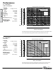
Performance Flow Rate Adjustable to . . . . . . . 0-46 gpm (174.1 lpm) Port Size Suction . . . . . . . . . . . . . . . . . 1" TRI-CLAMP Discharge . . . . . . . . . . . . . . . 1" TRI-CLAMP Air Inlet . . . . . . . . . . . . . . . . . . . . . 3/8" NPT Air Exhaust . . . . . . . . . . . . . . . . . 1/2" NPT Suction Lift Dry . . . . . . . . . . . . . . . . . . . . . . . . 16' (4.9 m) Wet . . . . . . . . . . . . . . . . . . . . . . . 31' (9.4 m) Max Solid Size (Diameter) . . . . . . . . . . . . . . . . . .
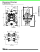
Dimensional Drawings E1 Metallic Bolted Dimensions in inches (mm dimensions in brackets) The dimensions on this drawing are for reference only. A certified drawing can be requested if physical dimensions are needed. 10.72 272.39 3/8" NPT AIR INLET 2.00 50.80 1/2" NPT AIR EXHAUST 10.93 277.60 13.63 346.15 14.44 366.79 4.81 122.22 9.27 235.36 1.56 39.62 .38 9.53 1.98 O.D. 50.29 SUCTION TRICLAMP FLANGE 7.81 198.37 .44 11.18 1/2" NPT AIR EXHAUST 4.81 122.22 3.56 90.47 9.27 235.36 1.70 43.
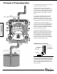
Principle of Pump Operation Air-Operated Double Diaphragm (AODD) pumps are powered by compressed air, nitrogen or natural gas. The main directional (air) control valve ① distributes compressed air to an air chamber, exerting uniform pressure over the inner surface of the diaphragm ②. At the same time, the exhausting air ③ from behind the opposite diaphragm is directed through the air valve assembly(s) to an exhaust port ④.
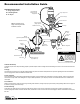
Recommended Installation Guide Available Accessories: 1. Surge Suppressor 2. Filter/Regulator 3. Air Dryer 1 Unregulated Air Supply to Surge Suppressor Surge Suppressor Pressure Gauge Shut-Off Valve Note: Surge Suppressor and Piping must be supported after the flexible connection.
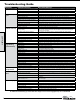
Troubleshooting Guide Symptom: Pump Cycles Once Pump Will Not Operate / Cycle 2: INSTAL & OP Pump Cycles and Will Not Prime or No Flow Potential Cause(s): Deadhead (system pressure meets or exceeds air supply pressure). Air valve or intermediate gaskets installed incorrectly. Bent or missing actuator plunger. Pump is over lubricated. Lack of air (line size, PSI, CFM). Check air distribution system. Discharge line is blocked or clogged manifolds.
Composite Repair Parts Drawing FUSION DIAPHRAGM ASSEMBLY 30 PHRAGM ASSEMBLY 31 21 30 22 22 Torque Setting: 300 in-lbs. 33 Torque Setting: 120 in-lbs. PTFE 2-PEICE DIAPHRAGM ASSEMBLY 23 22 21 23 3 21 25 4 11 Torque Setting: 120 in-lbs. PTFE 2-PEICE DIAPHRAGM ASSEMBLY 5 6 4 24 6 1 8 24 Torque Setting: 30 in-lbs. 19 9 2 7 19 2 12 10 12 32 14 16 Torque Setting: 300 in-lbs. 27 Torque Setting: 300 in-lbs.
3: EXP VIEW Composite Repair Parts List Item # 1 2 3 4 5 6 7 8 9 10 11 Qty. 1 1 1 1 1 1 1 2 1 1 1 4 Item # 12 13 14 15 16 17 18 19 Qty. 1 1 8 1 6 2 4 1 Item # Qty. 20 21 22 23 24 25 26 27 2 1 2 2 2 2 4 4 Item # 28 29 30 31 32 33 34 30 31 32 Qty. 4 2 16 16 16 1 1 8 8 8 9 • Model E1 Metallic Bolted Air Valve Assembly Description Part Number Valve Body Assembly (Includes items 1-11) 031.V005.
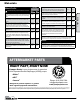
Written Warranty 5 - YEAR Limited Product Warranty Quality System ISO9001 Certified • Environmental Management Systems ISO14001 Certified Versa-Matic warrants to the original end-use purchaser that no product sold by Versa-Matic that bears a Versa-Matic brand shall fail under normal use and service due to a defect in material or workmanship within five years from the date of shipment from Versa-Matic’s factory. ~ See complete warranty at http://www.versamatic.com/pdfs/VM%20Product%20Warranty.
Genuine Parts, Real Value vs. Kit: Annual Savings = $1,299 Partial Repair Repair Kit Ordering Parts Kits Over Individual Components: • Reduces frequency of repairs • Reduces downtime • Reduces cost • Increase your uptime • Improve parts availability • Extended service life w w w . v e r s a m at i c .