
User Manual


8
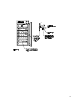
CONTROL PANEL OVERVIEW
4.1 Power Switch: The main power I/O (on/off) switch controls all power to the unit
and must be in the I/ON position before any systems are operational.
4.2 Main Temperature Control: The Main Temperature Control consists of the
digital display and UP/DOWN arrow pads for inputting set point temperatures and
calibration.
4.3 HEATING Lamp: This green pilot lamp in ON when the unit is heating up to set
point and is blinking when controlling temperature at set point.
4.4 Overtemperature Thermostat: Marked SET OVERTEMPERATURE, the
Thermostat is a completely independent control that acts as an override in the
event that the Main control fails in the ON position. The Thermostat will regulate
chamber temperature at approximately 1C above the set point of the Main
controller.
4.5 OVER TEMP Lamp: This red pilot lamp is On when the Overtemperature
Thermostat has taken control of the unit. Under normal operating conditions this
lamp should never be on.
4.6 Circuit Breaker: (Non-CE units) Located adjacent to the power cord, the circuit
breaker is an added measure of protection against power source variations that,
if tripped, can be reset by pushing in the button once the reason for the
interruption has been cleared.
4.7 Fuse: (CE units) Located adjacent to the power cord in place of the circuit
breaker. The fuse is an added measure of protection against power source
variations, and if blown must be replace once the source of the interruption has
been cleared.
Section
4