Version: V1.00.
iSmartTool Series User Manual Copyright Information Copyright © 2021 by SHENZHEN SMARTSAFE TECH CO.,LTD. (also called SMARTSAFE for short). All rights reserved. No part of this publication may be reproduced, stored in a retrieval system, or transmitted in any form or by any means, electronic, mechanical, photocopying and recording or otherwise, without the prior written permission. Statement: SMARTSAFE owns the complete intellectual property rights for the software used by this product.
iSmartTool Series User Manual Important Safety Precautions To avoid personal injury, property damage, or accidental damage to the product, read all of the information in this section before using the tool. DANGER • When an engine is operating, keep the service area well-ventilated or attach a building exhaust removal system to the engine exhaust system. Engines produce various poisonous compounds (hydrocarbon, carbon monoxide, nitrogen oxides, etc.
iSmartTool Series User Manual Automotive batteries contain sulfuric acid that is harmful to skin. In operation, direct contact with the automotive batteries should be avoided. Keep the ignition sources away from the battery at all times. Keep the tool dry, clean, free from oil, water or grease. Use a mild detergent on a clean cloth to clear the outside of the equipment when necessary. Keep clothing, hair, hands, tools, test equipment, etc. away from all moving or hot engine parts.
iSmartTool Series User Manual Table of Contents 1 Introduction........................................................................................................ 1 1.1 PACKAGE LIST.................................................................................................. 1 1.2 COMPONENTS & CONTROLS................................................................................... 4 1.3 TECHNICAL PARAMETERS.....................................................................................
iSmartTool Series User Manual 6.4 ABS BLEEDING............................................................................................... 28 6.5 TIRE PRESSURE MONITOR SYSTEM RESET.......................................................... 28 6.6 GEAR LEARNING.............................................................................................. 28 6.7 IMMO SERVICE............................................................................................... 28 6.8 INJECTOR CODING.................
iSmartTool Series User Manual 9.8 DIAGNOSTIC SOFTWARE CLEAR.......................................................................... 33 9.9 SETTINGS....................................................................................................... 34 10 FAQ...................................................................................................................
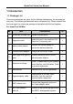
iSmartTool Series User Manual 1 Introduction 1.1 Package List Common accessories are same, but for different destinations, the accessories may vary. The following accessories are for reference only. Please consult from the local agency or check the package list supplied with this tool together. For iSmartTool 601Max No. Item Descriptions Qt. 1 iSmartTool 601Max tool Indicate the test result. 2 Diagnostic cable Collect the tool to the vehicle’s DLC (Data Link Connector) port.
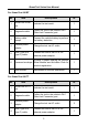
iSmartTool Series User Manual For iSmartTool 601BT No. Item Descriptions Qt. 1 iSmartTool 601BT tool Indicate the test result. 1 2 Diagnostic cable Collect the tool to the vehicle’s DLC (Data Link Connector) port. 1 3 Battery cable clamps Connect the vehicle battery to perform the battery detection. 1 4 External power adaptor Charge the tool via AC outlet.
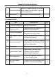
iSmartTool Series User Manual 5 A piece of paper bearing the product Password envelope Serial Number and Activation Code for product registration. 1 6 User manual 1 Instructions on the tool operations. For iSmartTool 601 No. Item Descriptions Qt. 1 iSmartTool 601Max tool Indicate the test result. 2 Diagnostic cable Collect the tool to the vehicle’s DLC (Data Link Connector) port. 1 3 External power adaptor Charge the tool via AC outlet.
iSmartTool Series User Manual 1.2 Components & Controls 2. LCD screen – Indicates the test Connects the diagnostic cable to the vehicle’s DLC (Data Link Connector) port. results. 7. Circular connector – Connects the 3. Printer – Prints the diagnostic reports or screenshots. battery tester clamps to perform battery detection. 4. USB Type A port – Connects the 8. Rear camera Videoscope or USB storage device. 9. Handgrip belt 5. USB Type C port – Connects the 10.
iSmartTool Series User Manual 1.3 Technical Parameters Operating system: Android Memory: 4GB Storage: 32GB Screen: 5.99 inch capacitive touch screen with a resolution of 1440 x 720 pixels Camera: Rear-facing 8.0MP camera Wi-Fi: 2.
iSmartTool Series User Manual 2 Initial Use 2.1 Charging & Turning On 1. Plug one end of the included USB cable into the USB Type C port of the tool, and the other end to the DC external power adaptor. 2. Plug the other end of the power adaptor to the AC outlet to start charging. 3. Press the POWER button to turn the tool on. Caution: Please use the included power adaptor to charge your tool.
iSmartTool Series User Manual 4. Close the paper cover and press it down until you hear a click. Note: The printer applies the thermal paper, which should be prevented from being heated before printing, otherwise, the paper would be no longer effective or printing results disappear. 2.3 Basic Operations Single-tap: To select an item or SMARTSAFE a program. Double-tap: To zoom in so that the text on a webpage appears in a column that fits your device’s screen.
iSmartTool Series User Manual then release it, the system will change into the target language. 2.5 Network Setup The tool has built-in Wi-Fi that can be used to get online. Once you’re online, you can register your tool, surf the Internet, send email, SMARTSAFE the remote diagnosis, and check for software updates etc. 5. On the home screen, tap Tablet Settings -> Network & Internet -> Wi-Fi. 6. Slide the Wi-Fi switch to ON, the tool starts searching for available wireless networks. 7.
iSmartTool Series User Manual Code (can be obtained from the password envelope), and then tap Activate. 3. Download diagnostic software: Tap OK to enter the update center to download all available software. B. If you have registered to be a member, input your name and password, and then tap Login to enter the main menu screen directly. Note: The tool has an auto-save function. Once the username and password are correctly entered, the system will automatically store it.
iSmartTool Series User Manual Reports: Manage the diagnostic report and recorded data. Update: Update vehicle diagnostic software and APK. Tablet setting: Configure the system settings of the tool. Videoscope: Check the unseen or unreachable parts or components. Personal center: Manage personal information; configure system settings of the application and logout etc. Feedback: Feedback the diagnostic issues or bugs to us for analysis and troubleshooting.
iSmartTool Series User Manual A. Opel, Volkswagen, Audi B. Honda C. Volkswagen D. Opel, Volkswagen, Citroen E. Changan F. Hyundai, Daewoo, Kia, Honda, Toyota, Nissan, Mitsubishi, Renault, Opel, BMW, Mercedes-Benz, Mazda, Volkswagen, Audi, GM, Chrysler, Peugeot, Regal, Beijing Jeep, Citroen and other most popular models If the DLC cannot be found, refer to the vehicle’s service manual for the location. 3.
iSmartTool Series User Manual adaptor. 3.3 Start Diagnostics Tap a corresponding diagnostic software logo, and then follow the on-screen instruction to access the diagnostic software. Take Demo (Version 15.32) as an example to demonstrate how to diagnose a vehicle. 1).Select diagnostic software version: Tap the DEMO to go to Step 2. 2). Select vehicle model (varies with different versions): Select the desired vehicle model. Here we take TOYOTA for example to demonstrate how to diagnose a vehicle. 3).
iSmartTool Series User Manual Explanation of terms: : Back to the Job menu. : Print the content of the current screen. : Exit the current program. Report: Save the current data in text format. Help: View the DTC help information. Compare Results: Tap to select the pre-repair report to compare. By comparison of the pre- and post- repair reports, you can easily identify which DTCs are cleared and which remain unfixed. Clear DTCs: Tap to clear the existing diagnostic trouble codes. 2.
iSmartTool Series User Manual Note: Different vehicle has different diagnostic menus. A. Read Fault Code This function displays the detailed information of DTC records retrieved from the vehicle’s control system. Caution: Retrieving and using DTCs for troubleshooting vehicle operation is only one part of an overall diagnostic strategy. Never replace a part based only on the DTC definition.
iSmartTool Series User Manual Explanation of terms: Freeze Frame: A snapshot of critical parameter values at the time the DTC is set. Help: View the help information. Code Search: Search for more information about the current DTC online. Report: Save the current data in text format. All reports are saved in Test report -> Health Report. B.
iSmartTool Series User Manual Notes: Tap to set the display style. indicates sticky top. B indicates this item will be displayed in Bold. A indicates this item will be displayed in Red. There are 3 types of display modes available for data viewing, allowing you to view various types of parameters in the most suitable way. Value – Display the parameters in texts and shows in list format. Graph – Display the parameters in waveform graphs.
iSmartTool Series User Manual items and save it as a sample Data Stream file. Save Sample: Save the running parameters as a data stream sample file. Note: Only data stream items with measurement units will be recorded. Report: Tap to save the current data in text format. All reports are saved in Test report -> Health Report. Record: Tap to start recording diagnostic data. Recorded live data can serve as valuable information to help you in troubleshooting of vehicle problems.
iSmartTool Series User Manual 4 Battery (only applies to iSmartTool 601BT & iSmartTool 601Max) 4.1 Battery Test Battery test is specifically designed to help car owner, repair workshop, battery factory determine whether the battery is normal or not. It supports various battery standards and specifications, including CCA, DIN, IEC, EN, JIS, SAE and GB etc. Two test modes (Out-of-car Inspection & In-car Inspection) are available and applicable to battery test. There are mainly 5 battery states as follows: 1.
iSmartTool Series User Manual 3. Tap to scan the barcode on the battery or manually input the code printed on the battery if necessary. Or tap Next Step to enter the next step. 4. Do appearance check of the battery or directly tap Next Step to ignore it. 5. Select the correct battery type, standard and capacity according to the battery name plate and tap Start the Detection. 6. After the detection is complete, the test result and battery state will appear on the screen.
iSmartTool Series User Manual Note: Where the SOC and SOH indicates the State of Charge and State of Health respectively. 4.1.2 In-car Inspection In-car inspection indicates that the battery connects to loading devices, such as engine, etc. In this mode, the following tests can be done in a sequence of battery test, start test and charging test.
iSmartTool Series User Manual including generator, rectifier, rectifier diode, etc. Through this test, we can know that the output voltage of the generator, the rectifier diode, and the charging current is normal or not respectively. 1. Connect one end of the included diagnostic cable to the DB15 diagnostic connector, and the other end to the vehicle’s DLC port. 2. Plug one end of the battery cable clamps into the circular connector of the tool.
iSmartTool Series User Manual 13.3-15.5V for imported vehicles. The voltage varies with different car models, so you have to judge based on related vehicle models. In general, the DC voltage is stable, but it also varies with different revolution speed. Starting voltage range: The value higher than 9.6V is regular, otherwise it is too low. Due to different situations, whether the starting voltage is higher or not does not mean the vehicles or batteries are faulty.
iSmartTool Series User Manual 5 TPMS (only applies to iSmartTool 601TT & iSmartTool 601Max) This module provides the ability to activate most OEM/Universal TPMS sensors, reprogram sensor IDs, retrieve/clear TPMS DTCs and relearn sensors, helping technicians quickly find out faulty TPMS and turn off MILs. In general, the following steps are required for the TPMS detection. 1. Enter TPMS. 2. Select vehicle manufacturer. 3. Select vehicle model and year. 4. Select the TPMS function*. 5.
iSmartTool Series User Manual the tool alongside the valve stem. 2. If the TPMS sensor requires tire deflation (of the order of 10PSI), then deflate the tire and place the tool alongside the stem while tapping Active. 5.2 Program TPMS Sensor This function allows users to program the sensor data to the specific sensor and replace faulty sensor with low battery life or one that is not functioning.
iSmartTool Series User Manual Note: If Auto is selected, the TPMS Relearn operation needs to be performed after programming all required sensors. Method 2 – Manual Create This function allows users to manually enter sensor ID. Users can enter the random ID or the original sensor ID, if it is available. 1. Select the wheel which needs to be programmed on the tool, place the sensor close to the TPMS antenna of the tool, and tap Manual. 2.
iSmartTool Series User Manual function, the tool will use the sensor information retrieved by the trigger function to program the sensor as default priority. 5.3 TPMS Learning This function is used to write the newly programmed sensor IDs into the vehicle’s ECU for sensor recognition. Relearn operation applies only when the newly programmed sensor IDs are different from the original sensor IDs stored in the vehicle’s ECU.
iSmartTool Series User Manual 6 Maintenance This module provides an easy dial to quickly access the most commonly performed service functions as follows.
iSmartTool Series User Manual 2. The brake pad indicator lamp is on. 3. The brake pad sensor circuit is short, which is recovered. 4. The servo motor is replaced. 6.3 Steering Angle Calibration This function enables you to reset the steering angle, after replacing the steering angle position sensor, replacing steering mechanical parts (such as steering gearbox, steering column, end tie rod, steering knuckle), performing four-wheel alignment, or recovering car body. 6.
iSmartTool Series User Manual control keys to normally use the car. It needs to be performed in the following cases: When the ignition switch key, ignition switch, combined instrument panel, ECU, BCM, or remote control battery is replaced. 6.8 Injector Coding This function enables you to write injector actual code or rewrite code in the ECU to the injector code of the corresponding cylinder, so as to more accurately control or correct cylinder injection quantity.
iSmartTool Series User Manual control the actions of regulating throttle (or idle engine) to adjust the amount of air intake. 6.12 Gearbox Matching This function enables you to complete the gearbox self-learning to improve gear shifting quality. It needs to be performed in the following cases: When the gearbox is disassembled or repaired. 6.13 AFS (Adaptive Front-lighting System) Reset This function enables you to initialize the adaptive headlamp system. 6.
iSmartTool Series User Manual control panel. 6.21 A/F Reset This function is applied to set or learn Air/Fuel ratio parameters. 6.22 Coolant Bleed Use this function to activate the electronic water pump before venting the cooling system. 6.23 Transport Mode In order to reduce power consumption, the following functions may be disabled, including limiting the vehicle speed, not waking up the door opening network, and disabling the remote control key, etc.
iSmartTool Series User Manual 7 Update This module enables you to update the diagnostic software & App and frequently used software. 7.1 Update Diagnostic Software & APP Go to Update on the Job Menu to enter the update center. Tap Update to start downloading. Once download is finished, the software packages will be installed automatically. 7.2 Renew Subscription If the software subscription is due or expires, the system will prompt you to renew your subscription.
iSmartTool Series User Manual 8 Videoscope This module allows you to check those unseen parts of engine, fuel tank, braking system. It needs to work with the compatible Videoscope device (sold separately). For more details, please refer to the User Manual included with the module. 9 Personal Center This function allows users to manage personal information and VCI. 9.1 VCI This option allows you to manage all your activated VCI devices. 9.
iSmartTool Series User Manual 9.9 Settings It enables you to make some application settings and view software version information etc. 1. Units of Measurement It is designed to configure the measurement unit. Metric System and English System are available. 2. Shop Information This option lets you define your print information. After inputting, tap Save. Once you saved the print information, it will be entered automatically in the “More Information” box every time you save the diagnostic report. 3.
iSmartTool Series User Manual 10 FAQ 1. How to save power? 1. Please turn off the screen while the tool keeps idle. 2. Set a shorter standby time. 3. Decrease the brightness of the screen. 4. If WLAN connection is not required, please turn it off. 5. Disable GPS function if GPS service is not in use. 2. Communication error with vehicle ECU? Please confirm: 1. Whether the VCI connector is correctly connected. 2. Whether ignition switch is ON. 3.
iSmartTool Series User Manual FCC Warnning: Any Changes or modifications not expressly approved by the party responsible for compliance could void the user's authority to operate the equipment. This device complies with part 15 of the FCC Rules. Operation is subject to the following two conditions: (1) This device may not cause harmful interference. (2) this device must accept any interference received, including interference that may cause undesired operation.
iSmartTool Series User Manual ISED Warnning: This device contains licence-exempt transmitter(s)/receiver(s) that comply with Innovation, Science and Economic Development Canada’s licence-exempt RSS(s). Operation is subject to the following two conditions: (1) This device may not cause interference. (2)This device must accept any interference, including interference that may cause undesired operation of the device.
iSmartTool Series User Manual Warranty THIS WARRANTY IS EXPRESSLY LIMITED TO PERSONS WHO PURCHASE SMARTSAFE PRODUCTS FOR PURPOSES OF RESALE OR USE IN THE ORDINARY COURSE OF THE BUYER’S BUSINESS. SMARTSAFE electronic product is warranted against defects in materials and workmanship for one year from date of delivery to the user.
iSmartTool Series User Manual THANK YOU FOR CHOOSING SMARTSAFE! If you have any questions or comments please contact: SHENZHEN SMARTSAFE TECH CO.,LTD. Addr: 3F, Building B, Qiao’an Technology Industrial Park, Guanlan, Longhua New District, Shenzhen Zip: 518110 Tel: 86-755-89589916 http://www.newsmartsafe.com Statement: SMARTSAFE reserves the rights to make any change to product designs and specifications without notice.