
Owners manual

6
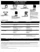
For 14" Diameter Tanks
For 16" Diameter Tanks
FOUR WHEEL HEAVY DUTY DOLLY
ASSEMBLY
(Not standard with all models)
Tools required:
(2) 1/2 inch open end wrenches, (2) 7/16 inch open end wrenches, or a socket set and a ham-
mer.
1. Insert 2
1
/
2
inch long bolt through center hole in rear frame, attach split lockwasher and nut
and tighten securely.
2. Attach handle brace to back of rear frame with 5/8 inch long machine screws, lockwash-
ers, and nuts. (Finger tighten only.)
3. Position main frame inside rear frame. Attach (2) 5/8 inch long machine screws, lockwash-
ers and nuts in both sides. Tighten securely.
4. Attach handle uprights, inside main frame (make sure buttons at top face inward) using 5/8
inch long machine screws, lockwashers and nuts. (Finger tighten only.) Align holes at top
of handle braces with holes in handle uprights. Attach with 1
1
/
4
inch long machine screws,
lockwashers and nuts. (Tighten securely.)
5. Go back and tighten machine screws at bottom of uprights and braces.
6. Attach caster sockets (open end down) to front of main frame using 5/8 inch long
machine screws, lockwashers and nuts. Insert casters into sockets.
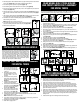
7. Slide basket adapters on handle.
8. See Figure 47 and Figure 48 for correct installation of adapters.
Handle
Handle
47
49
Tank
Basket
Basket
Adapter
Basket
Adapter
Pull Outward
on Basket
Handle
Handle
48
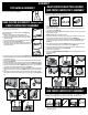
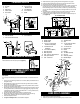
ITEM DESCRIPTION PART NO.
1 Cap nut 43002-99
2 8" Wheel 24250-10
3 Axle 24415-00
4 Rear frame 93921-00
5 Caster socket 75405-00
6 Front frame 93920-00
7 #8 x 1/2" lg. Screw 15015-99
8 1/4-20 x 3/4" lg. Machine screw 09029-99
9 1/4" Flatwasher 07003-99
10 1/4-20 Hex nut 13001-99
11 Caster 67736-00
1
2
4
3
5
Dolly
Hex
Nut
Tank
Machine
Screw
Flat
Washer
1
4
11
5
8
7
6
2
3
10
9
Bottom of Tank
1. Remove head from tank and place tank upside
down on a flat surface.
2. Place wheels on rear frame/axle assembly with
extended hub of wheel towards dolly frame and
place cap nuts on axle. Secure with hammer.
3. Insert caster socket into front frame and secure
with phillips head screw.
4. Place groove in front frame into lip of tank and
position so frame is directly above inlet.
5. Position grooves of rear frame into lip of tank
and align so rear and front frames engage.
6. Secure dolly frame to tank by placing machine screws
up through holes in dolly frame. Ensure head of screw
is fully recessed in area provided. After machine screw
is inserted, tighten with flatwasher and hex nut.
7. Insert caster in caster socket and apply downward
pressure until caster snaps into place.
8. Return vacuum to upright position. Attach carriage
handle to tank by inserting bolt through the center hole
of handle and tank, secure with nut provided. Attach
side handles with screws provided. Be sure to spread
ends of carriage handle when assembling to prevent
damage to tank.
9. Insert basket through center of carriage handle and
slide into place.
ITEM DESCRIPTION PART NO.
1 Metal tank handle 20882-00
2 Handle & hardware Pkg. 93555-96
(includes items 3-6)
3 Side tank handle 93551-00
4 #10 x 3/4" Screw hex head 15039-99
5 Bolt 1/4-20 x 1/2" 64012-99
6 1/4-20 Hex nut 13001-99
ITEM DESCRIPTION PART NO.
1 Cap nut 43002-99
2 8" Wheel 24250-10
3 Axle 24415-00
4 Rear frame 93921-00
5 Caster socket 75405-00
6 Front frame 93920-00
7 #8 x 1/2" lg. Screw 15015-99
8 1/4-20 x 3/4" lg. Machine screw 09029-99
9 1/4" Flatwasher 07003-99
10 1/4-20 Hex nut 13001-99
11 Caster 67736-00
1
2
4
3
5
Dolly
Hex
Nut
Tank
Machine
Screw
Flat
Washer
1
4
11
5
8
7
6
2
3
10
9
Bottom of Tank
1. Remove head from tank and place tank upside
down on a flat surface.
2. Place wheels on rear frame/axle assembly with
extended hub of wheel towards dolly frame and
place cap nuts on axle. Secure with hammer.
3. Insert caster socket into front frame and secure
with phillips head screw.
4. Place groove in front frame into lip of tank and
position so frame is directly above inlet.
5. Position grooves of rear frame into lip of tank
and align so rear and front frames engage.
6. Secure dolly frame to tank by placing machine screws
up through holes in dolly frame. Ensure head of screw
is fully recessed in area provided. After machine screw
is inserted, tighten with flatwasher and hex nut.
7. Insert caster in caster socket and apply downward
pressure until caster snaps into place.
8. Return vacuum to upright position. Attach carriage
handle to tank by inserting bolt through the center hole
of handle and tank, secure with nut provided. Attach
side handles with screws provided. Be sure to spread
ends of carriage handle when assembling to prevent
damage to tank.
9. Insert basket through center of carriage handle and
slide into place.
ITEM DESCRIPTION PART NO.
1 Metal tank handle 20882-00
2 Handle & hardware Pkg. 93555-96
(includes items 3-6)
3 Side tank handle 93551-00
4 #10 x 3/4" Screw hex head 15039-99
5 Bolt 1/4-20 x 1/2" 64012-99
6 1/4-20 Hex nut 13001-99
1. Cap nut
2. 8" wheel
3. Axle
4. Rear frame
5. Caster socket
6. Front frame
ITEM NUMBER & DESCRIPTION
1. Metal tank handle
2. Side tank handle
3. #10 x 3/4" Screw hex head
7. #8 x 1/2" lg. Screw
8. 1/4 - 20 x 3/4" lg.
Machine screw
9. 1/4" Flatwasher
10. 1/4 - 20 Hex nut
11. Caster
ITEM NUMBER & DESCRIPTION
4. Bolt 1/4 - 20 x 1/2"
5. 1/4 - 20 Hex nut
SIDE TANK HANDLE ASSEMBLY
(Not standard with all models)
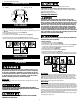
Attach side handles to tank with screws provided (Figure 46).
46
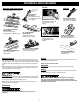
9. Attach handle onto uprights by pushing down and holding buttons in on uprights.
10. Place tank retaining bracket through slot and bolt in rear frame and screw on knob.
11. Slide bumper down over main dolly frame until it bottoms out.
12. Place axle upright on a hard surface and hammer on (1) cap nut. Place (1) wheel on axle
and slide down to cap nut. Slide axle through rear of frame and slide on other wheel.
Before assembling cap nut on other end of axle, be certain dolly is assembled correctly.
(You may place tank on dolly and tighten knob of retaining bracket to be sure of correct
assembly.)
13. After ensuring dolly is assembled correctly remove tank and place dolly on side with
installed cap nut on hard surface and hammer second cap nut on axle.
14. Place accessory basket on adapters and pull out on outer rim of basket and snap into
place (Figure 49).
1
10
7
14
15
2
3
23
6
5
12
13
23
4
15
22
19
18
15
17
8
9
5
16
5
15
21
11
20
1. Handle
2. Handle upright
3. Handle brace
4. 1/4 - 20 x 1
1
/4" Hex head
machine screw (Black)
5. 1/4" External tooth
lockwasher
6. 1/4 - 20 Hex nut (Black)
7. Rear dolly frame
8. Main dolly frame
9. 5/16 - 18 x 2
1
/2" Hex head bolt
10. 5/16" Split lockwash
11. 5/16 - 18 Hex nut
ITEM NUMBER & DESCRIPTION
12. Tank retainer bracket
13. Threaded knob
14. Axle
15. 1/4 - 20 x 5/8" Hex head
machine screw
16. 1/4 - 20 Hex nut
17. Caster socket
18. Caster
19. Bumper
20. 10" Wheel (25.4cm)
21. Cap nut
22. Accessory basket
23. Basket adapter
BAND DOLLY ASSEMBLY
(Not standard with all models)
1. Place casters into sockets on band assembly.
2. Place tank upside down and slip band assembly over lip on bottom of tank.