Main Menu Shure Brothers Incorporated 222 Hartrey Avenue Evanston IL 60202-3696 U.S.A. Model DFR11EQ User Guide ÁÁ ÁÁ Á Á ÁÁ ÁÁ Á ÁÁ ÁÁ ÁÁ ÁÁ Á DFR11EQ Digital Feedback Reducer and Graphic Equalizer With Software Interface for Windows * 1996, Shure Brothers Inc. 27A8523 (PJ) Printed in U.S.A.
Main Menu TABLE OF CONTENTS INTRODUCTION . . . . . . . . . . . . . . . . . . . . . . . . . . . . . . . . . . . . . . . . . . . . . . . . . . . . . . . . . . . . . . . . . . . . . . . . . . . . . . . . . 2 Features . . . . . . . . . . . . . . . . . . . . . . . . . . . . . . . . . . . . . . . . . . . . . . . . . . . . . . . . . . . . . . . . . . . . . . . . . . . . . . . . . . . . 2 Added Features When Interfaced with a Personal Computer . . . . . . . . . . . . . . . . . . . . . . . . . . . . . . . . . . . .
Main Menu INTRODUCTION The Shure Model DFR11EQ is a single channel signal processor that combines a feedback reducer and graphic equalizer in a single, half-rack enclosure. The DFR11EQ is designed to be placed in a sound reinforcement signal path to automatically detect and control acoustical feedback and equalize overall sound system response. The DFR11EQ is designed for installed sound reinforcement applications: theater, conference rooms, meeting halls, etc.
Main Menu THE DFR11EQ Overview Front Panel BYPASS Button and LED. Press this button to suspend feedback reducer operation and remove filters from the audio path. Does not affect the graphic equalizer. When the LED illuminates, the feedback reducer is bypassed. SIGNAL LED. Illuminates when input signal is present. Intensity varies with input signal level. CLIP LED. Illuminates when the input signal is within 6 dB of clipping. CLEAR Filters Button and LED.
Main Menu DIP Switches The DIP switches located on the rear panel are used for adapting the unit to the sound system requirements. Switches 5 through 10 change other available options, see the table below.
Main Menu DFR11EQ Theory Feedback and DFR11EQ Operation When acoustical feedback occurs in a sound system, it is because the gain of the system is too high. Since no sound system (microphones, loudspeakers, room acoustics, etc.) has an absolutely flat frequency response, feedback will occur at specific frequencies before others; these are the frequencies with the most gain.
Main Menu Fixed and Dynamic Notch Filters The DFR11EQ can control the notch filters as either dynamic or fixed. The DFR11EQ’s 10 notch filters are factory preset as 5 fixed and 5 dynamic filters. There is no difference between dynamic and fixed filters until all 10 filters have been set. After all 10 notch filters are set and a new feedback frequency is detected, the DFR11EQ will remove the oldest set dynamic filter and re-deploy it at the new feedback frequency. The fixed filters remain unchanged.
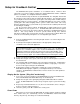
Main Menu Setup for Feedback Control The DFR11EQ will operate stand-alone as a feedback reducer. However, when connected to a personal computer running the supplied DFR11EQ software, additional options are available. See Computer Interface for details. There are two basic ways in which to set-up the DFR11EQ: The “Ring Out” method and the “Insurance Policy” method. Both are valid for different situations.
Main Menu Connecting the DFR11EQ in a Sound System The DFR11EQ should be placed where an equalizer would be in a signal path — it should be the final piece of equipment a sound signal passes through before going to a power amplifier. Other signal processors (for example, delay or reverb effects devices) should be placed before the DFR11EQ along the signal path. The following four diagrams show typical connections.
Main Menu Inserted in an Input Channel If only a single microphone is creating feedback problems, the DFR11EQ can be inserted on that channel alone. This is especially useful for wireless microphones, because the constant movement of a performer may bring the microphone too close to the sound reinforcement loudspeakers.
Main Menu COMPUTER INTERFACE Overview This section describes the Windows based computer interface software which allows you to utilize the full features of the Shure DFR11EQ. By connecting the DFR11EQ to your computer, you can access additional control features to customize the operating characteristics of the feedback filters. The computer interface also allows access to the built-in digital, 30-band, 1/3-octave, constant-Q, graphic equalizer.
Main Menu Networking Multiple DFR11EQs via the Shure Link Interface Up to 16 DFR11EQ’s can be linked together and controlled from a single computer. Each unit comes supplied with one 5-pin DIN cable for linking. Ñ Ñ ÑÑÑÑ ÑÑ DFR11EQ #1 LINK IN TO COMPUTER ÑÑÑ Ñ ÑÑ Ñ ÑÑÑ DFR11EQ #2 LINK OUT LINK OUT LINK IN ÑÑÑ Ñ Ñ ÑÑÑ ÑÑ DFR11EQ #3 LINK OUT LINK IN 1.
Main Menu Software Functions Main Menu Bar. Through the main menu bar, you can configure the computer connection to the DFR11EQ, and access other windows for configuring the DFR11EQ, setting filters, and saving scenes. Feedback Reducer Panel. The Feedback Reducer Panel contains many of the same controls available on the front panel of the DFR11EQ.
Main Menu Using the Feedback Reducer Panel Feedback Reducer (DFR) Bypass Button and LED Pressing the DFR bypass button suspends the feedback reducer operation and removes its filters from the audio path. It does not affect the graphic equalizer. When the LED illuminates, the feedback reducer is bypassed. This is identical to the front panel BYPASS button and LED. EQ Bypass Button and LED Pressing the EQ bypass button removes the graphic equalizer filters from the audio path.
Main Menu Using the Graphic Equalizer Adjusting Bands The DFR11EQ graphic equalizer looks and functions just like a conventional graphic equalizer. Each slider controls a 1/3-octave band centered around the frequency indicated above each slider. When a slider is selected, the center of the slider turns green. There are two ways to adjust the sliders: Using the mouse pointer... drag and drop the slider to the desired level.
Main Menu Viewing Response Curves DFR Response Curves Clicking on the DFR button displays the feedback filter frequency response curve on the graph. This curve shows the response of all deployed feedback filters. Here you can check the frequency and depth of each filter. EQ Response Curves Clicking on the EQ button displays the graphic equalizer frequency response curve on the graph. Use this curve as an aid in setting up the graphic equalizer.
Main Menu Accessing Connected DFR11EQs Configuring the Computer Serial Port 1. Launch the DFR11EQ software. 2. Click on Setup in the main menu bar. 3. Click on the COM port option of the drop-down menu. 4. In the DFR11EQ Serial Port window, select an available COM port on the computer. 5. Click on the OK button. NOTE: The COM port selection is saved in the DFR11EQ file, and will not need to be selected again unless you need to change the hardware configuration.
Main Menu DFR11EQ Settings The DFR11EQ Settings window contains options for controlling the DIP switches and setting fixed and dynamic filters. To access the DFR11EQ Settings window: 1. Click on Options in the main menu bar. 2. Select the DFR11EQ Settings... option of the drop-down menu. DIP Switch Override and Disable Clicking on the DIP switches override and disable box disables the Filter Bandwidth, EQ Defeat, and Front Panel Lock/Unlock DIP switches to prevent tampering.
Main Menu Scenes Once a DFR11EQ has been set up with a desired combination of settings, they can be stored on disk as a Scene. Although the DFR11EQ automatically saves the current scene in internal memory, other scenes can be saved to disk. Scenes are useful for reducing setup time when multiple units require similar settings. Scenes are also useful for multi-purpose sound system, or events which require changing settings “on the fly”. Up to 16 events may be stored on the computer for later recall.
Main Menu APPENDICES Appendix A. Specifications Weight 930 g (2.5 lbs) Frequency Response 20 to 20k Hz ± 1.
Main Menu Appendix B. Rack Mounting the DFR11EQ The DFR11EQ comes in a 1/2-rack chassis specially designed for sturdiness. The sagging and bending found in most 1/2-rack designs is eliminated — the brackets and straddle bars are designed to ensure that the units will be installed securely. WARNING: Do not torque the screws too tightly, or the chassis may be damaged. Single Unit ÑÑ ÑÑ ÑÑ ÑÑÑÑÑ Ñ ÑÑ ÑÑ ÑÑ ÑÑÑÑÑ Ñ ÑÑÑ Ñ ÑÑ ÑÑÑÑ Ñ Ñ Ñ ÑÑÑ ÑÑ ÑÑ Ñ ÑÑ ÑÑ Ñ ÑÑÑÑÑÑÑ ÑÑÑÑÑÑ ÑÑÑÑÑ ÑÑÑ 1.
Main Menu Appendix C. Connectors and Cables NOTE: Except for the Shure Link cable, none of the cables shown come supplied with the DFR11EQ.
Main Menu 1/ -in. 4 to 1/4 -in.
Main Menu XLR (female) to 1/4 -in.
Main Menu Digital Connectors and Cables Computer Interface — 9-Pin to 9-Pin RS-232 Cable 5 3 1 4 2 1 3 2 5 4 9-PIN FEMALE TO COMPUTER 6 7 8 9 COMPUTER 9-PIN RS-232 CONNECTOR MALE 8 6 9 7 1 3 5 2 4 5 3 4 1 2 9-PIN MALE TO DFR11EQ FUNCTION PIN # — RX TX DTR GND DSR RTS CTS — 1 2 3 4 5 6 7 8 9 9 7 8 6 DFR11EQ RS-232 CONNECTOR FEMALE 7 9 6 8 Computer Interface — 9-Pin to 25-Pin RS-232 Cable 13 11 9 7 5 3 1 12 10 8 6 4 2 1 3 2 5 4 9 7 6 8 11 13 10 12 FUNCTION 25-PIN FEMALE TO COMPUTER
Main Menu Appendix D. Warranty Warranty Shure Brothers Inc. (“Shure”) hereby warrants that these products will be free from defects in material and workmanship for a period of one year from the date of purchase. At its option, Shure will repair or replace the defective product and promptly return it to you, or refund the purchase price. Retain proof of purchase to validate the purchase date and return it with any warranty claim.
Main Menu Notes 26
Main Menu The Sound of Professionals...Worldwide Shure Brothers Incorporated 222 Hartrey Avenue Evanston, IL 60202–3696 U.S.A.