Model DP11EQ User’s Guide DP11EQ Dynamics Processor, Equalizer, and Delay with Windows Software E2006, Shure Incorporated 27A8630 (Rev.
TABLE OF CONTENTS INTRODUCTION . . . . . . . . . . . . . . . . . . . . . . . . . . . . . . . . . . . . . . . . . . . . . . . . . . . . . . . . . . . . . . . . . . . . . . . . . English – 2 Hardware Features . . . . . . . . . . . . . . . . . . . . . . . . . . . . . . . . . . . . . . . . . . . . . . . . . . . . . . . . . . . . . . . . . . . . . . English – 2 Software Features . . . . . . . . . . . . . . . . . . . . . . . . . . . . . . . . . . . . . . . . . . . . . . . . . . . . . . . . . . . . . . . . . . . .
INTRODUCTION DATA The Shure Model DP11EQ is a single-channel, digital signal processor that combines a comprehensive dynamics processor, two parametric equalizers, and a delay in a single, half-rack enclosure. The DP11EQ can function as a gate, expander, Automatic Gain Control (AGC) leveler, compressor, limiter, and no overshoot peak limiter. All of these features are accessed via the supplied Windows* software.
DP11EQ HARDWARE Overview Front Panel DATA Ê ËÌ Ê Ë Ì Í BYPASS Button and LED. Press this button to suspend all signal processing from the audio path. When the LED illuminates, the dynamics processor, delay, and the equalizers are bypassed. SIGNAL LED. Illuminates when input signal is present. Intensity varies with input signal level. CLIP LED. Illuminates when the input signal is within 6 dB of clipping. Í Î Ï Î Ï Dynamic Gain Meters.
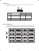
DIP Switches The DIP switches located on the rear panel are used for adapting the unit to the sound system requirements. See the table below. DIP SWITCH FUNCTION 1–4 Device ID 5–8 unused POSITION UP DOWN see below see below — — 9 Output Sensitivity +4 dBu –10 dBV 10 Input Sensitivity +4 dBu –10 dBV Shure Link Device ID When multiple DP11EQ s are linked, each one must be assigned a unique Device ID, 0 through 15. DIP switches 1 through 4 on the rear panel are used to set the Device ID.
Audio Connections The DP11EQ is a flexible unit which can be used in almost any part of a sound system. It can be placed directly in an input channel’s insert and used as an equalizer solely for that microphone. Or, it can be placed at a mixer subgroup insert, where it can act as a compressor, equalizer, and noise gate for a group of microphones.
Input Insert The DP11EQ can be placed directly on a single microphone insert to process the signal for that microphone only. This is a common location for an leveler.
DP11EQ SOFTWARE Introduction This section describes the Windows-based computer interface software which allows you to control the Shure DP11EQ . The software controls a dynamics processor which can operate as a gate, expander, leveler, compressor, limiter, and no overshoot peak limiter. There are parametric equalizers placed before and after the dynamics processor. In addition, there is a digital delay which can add up to 1.3 seconds of delay from input to output.
The Shure Program Group The Shure program group contains the main application icon, a Windows Help file, and a Readme file with the most up-to-date information. To launch the application, double-click on the DP11EQ icon. This group will also contain other Shure software stored on your hard drive. Configuring the Computer Serial Port 1. Launch the DP11EQ software. 2. Click on Communications in the main menu bar. 3. Click on the COM port option of the drop-down menu. 4.
Overview Main Control Panel. In the main control panel, there is button for muting the sound. There is also a button for bypassing overall processing, allowing you to hear the unaffected sound. There is also a Processor Select virtual signal path which allows access to the control panels for the separate processes. There is also a Dynamic Gain meter corresponding to the LEDs on the front panel of the DP11EQ. The Connect button accesses any units connected to a computer.
MAIN CONTROLS The top panel contains the main controls for the DP11EQ software. CURRENT DEVICE ID SCENE NAME UNIT NAME STATUS Main Menu. The main menu contains options for connecting, storing and recalling scenes, and networking with other DP11EQs and DFR11EQs. There is also a help file for online assistance. MUTE Button and LED. This button mutes the audio output of the DP11EQ. The LED is red when muted. BYPASS Button and LED. This button removes all processing from the signal path.
DYNAMICS PROCESSOR Dynamic range is the difference between the loudest and quietest levels of an audio signal. Controlling dynamic range plays an important role in good audio quality. Using the DP11EQ Dynamics Processor, you can control the dynamics of a sound system to improve audio quality.
Dynamics Parameters The edit boxes are used to adjust the parameters of each dynamics process. This section gives general definitions of the parameters. See Dynamics Processes for more specific information. THRESHOLD. The Threshold parameter determines the input level at which dynamics processing begins. For the gate and the expander, processing is activated by signal levels below the threshold. The AGC, the compressor, the limiter, and the peak limiter are triggered by signal levels above the threshold.
Dynamics Processes Gate Definition: A gate mutes an input signal when it drops below a user defined threshold. Every sound system has a certain amount of noise or hiss. Some of this noise is in the background (the hissing of air conditioners), and some may be caused by electrical sources affecting the equipment (electromagnetic hum caused by fluorescent lights). This noise and hiss is usually at such a low level that it is drowned out when there is program material present.
AGC Leveler Definition: The AGC leveler (AGC stands for Automatic Gain Control) automatically lowers or raises the signal level for sounds of varying loudness in order to create a more consistent volume. Application: The leveler can be used for podium and lectern microphones, where it is desirable to maintain a constant volume level when the talker may be moving back and forth from the microphone.
Compressor Definiton: A compressor reduces the dynamic level of an input audio signal by an amount determined by the ratio setting (usually less than 10:1). Typically, a compressor has a slower reaction time than a limiter. Application: Compression can be used in order to scale a signal with a wide dynamic range to audio equipment with a smaller dynamic range (amplifier, loudspeaker, tape recorder, etc.).
No Overshoot Peak Limiter Definition: The no overshoot peak limiter has the ratio fixed at infinity to one (∞:1), uses fast time constants and inserts 1 millisecond signal path delay, allowing the gain reduction to act instantaneously, without audible clipping artifacts, once the input level goes above the threshold. With the no overshoot peak limiter, no peaks will pass through the system, yet the harshness of clipping is avoided.
PARAMETRIC EQUALIZER The DP11EQ also contains two parametric equalizers, with up to 11 parametric filters possible. These equalizers can be used for tuning out feedback or other anomalies in the frequency response of the acoustics of a room or sound system. There are high- and low-frequency rolloff/shelf filters, and parametric filters with adjustable frequency, gain, and width. Parametric filters are represented as dots, while the high- and low-frequency filters are represented as squares.
Setting and Adjusting Parametric Filters Point and click on a filter. It will change colors to show that it is selected. Then, drag the filter by the center to the desired frequency and gain. A parametric filter can be used to cut or boost over a desired bandwidth. Notice that each filter dot also has wings with two smaller dots. drag these to adjust the Q, or width, of the filter to affect a smaller or larger bandwidth.
Response Graph This section describes how to use the Response Graph, which displays the frequency response for the DP11EQ. Snapshots A helpful feature of the response graph is the ability to take snapshots of a frequency response curve. A snapshot allows you to view a trace of the original response curve while making changes. This is an effective setup tool.
IN/OUT Meters and Output Control The IN and OUT level meters located next to the response curve graph display the levels of the input and output for the selected equalizer in dB. When the levels indicate OVR (over), the unit is clipping. This is a useful tool for observing net gain for the equalization settings. To compensate, you can use the OUTPUT slider located near the output controls. Raising or lowering this slider will raise or lower the gain of the output.
DELAY There are some potential problems with the arrival of sound in systems utilizing multiple loudspeakers. The DP11EQ Delay is designed to solve two of these problems: remote speaker alignment and phase cancellation. Delay for Solving Remote Speaker Alignment Problems ÑÑ AMPLIFIER DP11EQ WITH DELAY ÑÑ AMPLIFIER ÑÑ Ñ ÑÑÑ ÑÑ B AMPLIFIER A Ñ Ñ Ñ MIXER AMPLIFIER MIXER Problem: Illustration A — Some larger sound systems may utilize loudspeaker fill systems.
Setting Delay by Time To access the Delay window, click on the DELAY button in the virtual signal path. Then set the delay in milliseconds, click on the ↑ and ↓ buttons next the Delay box, or type the amount in the box. Setting Delay by Distance Setting delay by distance is very easy, but you should account for air temperature. As the temperature gets hotter the speed at which sound travels increases, so the delay time decreases.
SHURE LINK NETWORKS Shure Link Connections Up to 16 Shure Link devices can be linked together and controlled from a single computer. Each unit comes supplied with one 5-pin DIN cable for linking. ÑÑÑ ÑÑ DP11EQ #1 LINK IN TO COMPUTER ÑÑ ÑÑ DP11EQ #2 LINK OUT LINK IN LINK OUT Ñ ÑÑÑ DFR11EQ LINK OUT LINK IN 1. Assign each unit a Device ID (0 through 15) via the DIP switches on the rear panel (see Shure Link Device ID, in the Hardware section of this manual).
Shure Link Device Selection In order to access a device in a Shure Link network: 1. Click on Device in the main menu. 2. In the Device menu, click on the desired Device ID. The Device ID will appear beside the DP11EQ heading in the title bar at the top of the main window, indicating that the unit with that Device ID will receive computer commands. Naming a DP11EQ Devices can be named... In order to name a connected DP11EQ in a network: 1. Click on Device in the main menu of the Main Control Panel. 2.
Settings Settings for individual panels can be stored separately, as well. Settings are saved on disk with extensions which indicate the settings type: .DYN indicates dynamics, .PEQ indicated parametric equalizer, and .DLY indicates delay. To Save Settings to Disk To save the setting from the dynamics, delay, or either equalizer panel: 1. Click on File in the menu bar of the current panel. 2. Select the Save Settings... option of the drop-down menu. 3.
Printing DP11EQ Settings If you are documenting a sound system, the DP11EQ software offers the option of printing out a hardcopy report showing the settings of a selected unit. To print out a hardcopy of this report: 1. Click on File in the main menu bar of the Main Control Panel. 2. Click on Print... 3. Select any of the desired print options available. 4. Click on the button of the Name: field to display a drop-down list of available printers, then select a printer. 5. Click on the OK button.
CERTIFICATIONS Weight 930 g (2.05 lbs) DP11EQ : UL LISTED and cUL LISTED to UL 813 and CSA C22.2 No. 1. Authorized under Verification provision of FCC Part 15 as a Class B Digital Device. DP11EQ E: Conforms to European Union Directives, eligible to bear CE marking. Meets European Union Low Voltage Requirements: VDE GS-Certified to EN 60 950. Meets European Union EMC Emissions Requirements: EN 50 081-1 (1992) [EN 55022]. Meets European Union EMC Immunity Requirements EN 50 082–1 (1992).
APPENDIX B. RACK MOUNTING THE DP11EQ The DP11EQ comes in a 1/2-rack chassis specially designed for sturdiness. The sagging and bending found in most 1/2-rack designs is eliminated — the brackets and straddle bars are designed to ensure that the units will be installed securely. WARNING: Do not torque the screws too tightly, or the chassis may be damaged. Single Unit ÑÑ ÑÑ ÑÑ ÑÑÑÑÑ ÑÑÑ Ñ ÑÑ ÑÑ ÑÑÑÑÑÑ ÑÑÑÑÑÑ ÑÑÑÑÑ ÑÑÑ ÑÑÑÑÑÑ ÑÑÑÑ ÑÑÑ Ñ ÑÑ ÑÑ Ñ ÑÑ ÑÑ ÑÑÑÑÑÑ ÑÑÑÑÑ DATA 1.
APPENDIX C. CONNECTORS AND CABLES NOTE: Except for the Shure Link cable, none of the cables shown come supplied with the DP11EQ .
1/ -in. 4 to 1/4 -in. Balanced SLEEVE RING – + – TIP SLEEVE RING TIP 1/ -in.
XLR (female) to 1/4 -in. Balanced PIN 2 PIN 1 PIN 3 + – SLEEVE RING – TIP S S S S S TYPICAL APPLICATIONS Mixer Line Out to DP11EQ Input DP11EQ Output to Amplifier Input DP11EQ Output to Mixer Sub Return Mixer Send to DP11EQ Input Mixer Sub Send to DP11EQ Input S S S S S TYPICAL APPLICATIONS Mixer Line Out to DP11EQ Input DP11EQ Output to Amplifier Input DP11EQ Output to Mixer Sub Return Mixer Send to DP11EQ Input Mixer Sub Send to DP11EQ Input + XLR (female) to 1/4 -in.
Digital Connectors and Cables Computer Interface — 9-Pin to 9-Pin RS-232 Cable 5 3 1 4 2 1 3 2 5 4 9-PIN FEMALE TO COMPUTER 6 8 7 9 COMPUTER 9-PIN RS-232 PORT ( MALE) 8 6 9 7 1 3 5 2 4 5 3 4 1 2 9-PIN MALE TO DP11EQ FUNCTION PIN # — RX TX DTR GND DSR RTS CTS — 1 2 3 4 5 6 7 8 9 9 7 8 6 DP11EQ RS-232 PORT (FEMALE) 7 9 6 8 Computer Interface — 9-Pin to 25-Pin RS-232 Cable 13 11 9 7 5 3 1 12 10 8 6 4 2 1 3 2 5 4 9 7 6 8 11 13 10 12 FUNCTION 25-PIN FEMALE TO COMPUTER 14 16 18 20 22
APPENDIX D. KEYBOARD CONTROLS There are a number of keyboard controls which you can use in instead of a mouse.
IN/OUT Meters and OUTPUT Slider Controls RESET the OUTPUT slider: Turn the IN/OUT meters ON and OFF: or FINE ADJUST the output gain: or COARSE ADJUST the output gain: Parametric Equalizer Controls RESET a selected parametric filter: CREATE a new parametric filter: FINE ADJUST the FREQUENCY of a parametric filter: or COARSE ADJUST the FREQUENCY of a parametric filter: or FINE ADJUST the GAIN of a parametric filter: or COARSE ADJUST the GAIN of a parametric filter: or or ADJUST the WIDTH of a pa
SHURE Incorporated http://www.shure.com United States, Canada, Latin America, Caribbean: 5800 W. Touhy Avenue, Niles, IL 60714-4608, U.S.A. Phone: 847-600-2000 U.S.