TEC Controller Unit Conditioner - Fan Coil Unit Cooling and Heating, Application 2051 Application Note 140-1137 2014-05-01 Building Technologies
Table of Contents Overview ........................................................................................................................4 Hardware Inputs ..............................................................................................................5 Hardware Outputs ...........................................................................................................5 Ordering Notes ..............................................................................................
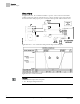
Overview Hardware Inputs Overview In Application 2051, the controller modulates separate valves in the fan coil unit for cooling and heating. The fan coil unit also has a fan to circulate room air. In order for the fan coil unit to work properly, the central plant must provide chilled and hot water. Application 2051 -- Fan Coil Unit Cooling and Heating Control Diagram. Application 2051 Control Schedule. NOTES: 1. See Control Temperature Setpoints. 2. See Heating/Cooling Switchover.
Overview Hardware Inputs Hardware Inputs Analog l Auxiliary temperature sensor (optional) Room temperature sensor l Room temperature setpoint dial (optional) l Digital l l Night mode override (optional) Wall switch (optional) Hardware Outputs Analog l None Digital l Fan (switched 24 Vac, pilot duty) Cooling valve actuator l Heating valve actuator (floating control) l Ordering Notes 540-110N Siemens TEC Unit Conditioner Controller 5 Siemens Industry, Inc.
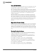
Sequence of Operation Control Temperature Setpoints Sequence of Operation The following paragraphs present the sequence of operation for the Siemens TEC Unit Conditioner (Fan Coil) Controller. Control Temperature Setpoints This application has a number of different room temperature setpoints (DAY HTG STPT, NGT CLG STPT, RM STPT DIAL, etc.). The application actually controls using the CTL STPT.
Sequence of Operation Room Temperature and CTL TEMP CTL STPT is calculated as follows: With Deadband Disabled: CTL STPT = Dial value With Deadband enabled in Heat Mode: CTL STPT = Dial value – 0.5 ∗ Deadband (limited between the value of RM STPT MIN and RM STPT MAX) With Deadband enabled in Cool Mode: CTL STPT = Dial value + 0.5 ∗ Deadband (limited between the value of RM STPT MIN and RM STPT MAX). NOTE: If RM STPT DIAL is failed, it maintains the last known value.
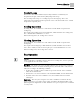
Sequence of Operation Day and Night Modes Day and Night Modes The day/night status of the space is determined by the status of DAY.NGT. The control of this point differs depending on whether the controller is monitoring the status of a wall switch or if the controller is connected to a field panel. When a wall switch is physically connected to the termination strip on the controller DI 2 (see the Control Diagram(s), and WALL SWITCH = YES, the controller monitors the status of DI 2.
Sequence of Operation Control Loops Control Loops The Siemens TEC Unit Conditioner (Fan Coil) Controller is controlled by two Proportional, Integral, and Derivative (PID) temperature loops. The two temperature loops are a cooling loop and a heating loop. The active temperature loop maintains room temperature at the value in CTL STPT. See Control Temperature Setpoints [➙ 6]. Cooling Operation In cooling mode, the controller uses CTL STPT and CTL TEMP as inputs for the cooling loop.
Sequence of Operation Calibration Calibration During normal operation: To ensure that the damper and valves open and close fully, the controller will provide additional opening and closing time when commended DMPR COMD or VLV 1 COMD and VLV 2 COMD = 100% and 0%. The controller regularly calibrates the valve(s) based on the value of CAL TIMER. A value of 12 indicates that the controller will calibrate the valve(s) once every 12 hours.
Sequence of Operation Wiring Diagram Wiring Diagram CAUTION The controller’s DOs control 24 Vac loads only. The maximum rating is 12 VA for each DO. An external interposing relay is required for any of the following: • VA requirements higher than the maximum • 110 or 220 Vac requirements • DC power requirements • Separate transformers used to power the load (for example part number 540-147, Terminal Equipment Controller Relay Module) Application 2051 – Fan Coil Unit Cooling and Heating.
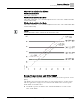
Application 2051 Point Database Application 2051 Point Database Point Number Descriptor Factory Default (SI Units)2) Eng Units (SI Units) Slope (SI Units) Intercept (SI Units) On Text Off Text 1 CTLR ADDRESS 99 -- 1 0 -- -- 2 APPLICATION 2090 -- 1 0 -- -- {04} ROOM TEMP 74.0 (23.44888) DEG F (DEG C) 0.25 (0.14) 48.0 (8.88888) -- -- {05} HEAT.COOL COOL -- -- -- HEAT COOL 6 DAY CLG STPT 74.0 (23.44888) DEG F (DEG C) 0.25 (0.14) 48.0 (8.
Application 2051 Point Database Point Number Descriptor Factory Default (SI Units)2) Eng Units (SI Units) Slope (SI Units) Intercept (SI Units) On Text Off Text 51 MTR 1 TIMING 130 SEC 1 0 -- -- {52} VLV 2 COMD 0 PCT 0.4 0 -- -- {53} VLV 2 POS 0 PCT 0.4 0 -- -- 55 MTR 2 TIMING 130 SEC 1 0 -- -- 56 MTR1 ROT ANG 90 -- 1 0 -- -- 57 MTR2 ROT ANG 90 -- 1 0 -- -- 58 MTR SETUP 0 -- 1 0 -- -- 59 DO DIR.
Issued by Siemens Industry, Inc. Building Technologies Division 1000 Deerfield Pkwy Buffalo Grove IL 60089 Tel. +1 847-215-1000 Document ID 140-1137 Edition 2014-05-01 © 2014 Copyright Siemens Industry, Inc. Technical specifications and availability subject to change without notice.