
Application

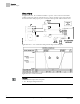
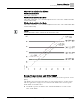
Table Of Contents

Sequence of Operation
Day and Night Modes
8
Siemens Industry, Inc. Application Note, App 2051 140-1137
2014-05-01
Day and Night Modes
The day/night status of the space is determined by the status of DAY.NGT. The control
of this point differs depending on whether the controller is monitoring the status of a
wall switch or if the controller is connected to a field panel.
When a wall switch is physically connected to the termination strip on the controller DI
2 (see the Control Diagram(s), and WALL SWITCH = YES, the controller monitors the
status of DI 2.) When the status of DI 2 is ON (the switch is closed), then DAY.NGT will
be set to DAY indicating that the controller is in day mode. When the status of DI 2 is
OFF (the switch is open), then DAY.NGT will be set to NIGHT indicating that the
controller is in night mode.
When WALL SWITCH = NO, the controller does not monitor the status of the wall
switch, even if one is connected to it. In this case, if the controller is operating stand-
alone, then the controller stays in day mode all the time. If the controller is operating
with centralized control (that is, it is connected to a field panel), then the field panel can
send an operator or PPCL command to override the status of DAY.NGT. See
Powers
Process Control Language (PPCL) User’s Manual
(125-1896) and
Field Panel User’s
Manual
(125-3019) or
BACnet Field Panel User’s Manual
(125-3020) for more
information.
Night Mode Override Switch
If an override switch is present on the room temperature sensor and a value (in hours)
other than zero has been entered into OVRD TIME, pressing the override switch will
reset the controller to DAY operational mode for the time period that is set in OVRD
TIME. The status of NGT OVRD changes to DAY. After the override time elapses, the
controller returns to night mode and the status of NGT OVRD changes back to NIGHT.
The override switch on the room sensor will only affect the controller when it is in night
mode.
Heating/Cooling Switchover
The heating/cooling switchover determines whether the controller is in heating or
cooling mode by monitoring the room temperature and the demand for heating and
cooling (as determined by the temperature control loops).
If the following conditions are met for the length of time set in SWITCH TIME, the
controller switches from heating to cooling mode by setting HEAT.COOL to COOL:
l HTG LOOPOUT < SWITCH LIMIT.
l CTL TEMP > CTL STPT by at least the value set in SWITCH DBAND.
l CTL TEMP > the appropriate cooling setpoint minus SWITCH DBAND.
If the following conditions are met for the length of time set in SWITCH TIME, the
controller switches from cooling to heating mode by setting HEAT.COOL to HEAT:
l CLG LOOPOUT < SWITCH LIMIT.
l CTL TEMP < CTL STPT by at least the value set SWITCH DBAND.
l CTL TEMP < the appropriate heating setpoint plus SWITCH DBAND.