
Application

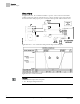
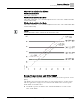
Table Of Contents

Sequence of Operation
Control Loops
9
Siemens Industry, Inc. Application Note, App 2051 140-1137
2014-05-01
Control Loops
The Siemens TEC Unit Conditioner (Fan Coil) Controller is controlled by two
Proportional, Integral, and Derivative (PID) temperature loops.
The two temperature loops are a cooling loop and a heating loop. The active
temperature loop maintains room temperature at the value in CTL STPT. See Control
Temperature Setpoints [➙ 6].
Cooling Operation
In cooling mode, the controller uses CTL STPT and CTL TEMP as inputs for the
cooling loop.
The output of the cooling loop is CLG LOOPOUT, which modulates the cooling valve;
VLV 1 COMD. HTG LOOPOUT is set to 0%.
When in heating mode, the cooling valve is closed.
Heating Operation
In heating mode, the controller uses CTL STPT and CTL TEMP as inputs for the
heating loop.
The output of the heating loop is HTG LOOPOUT, which modulates the hot water
valve, VLV 2 COMD, in order to warm up the space. CLG LOOPOUT is set to 0%.
When in cooling mode, the heating valve is closed.
Fan Operation
NOTE:
If this application is controlling a damper instead of a cooling valve, the fan operation
is not applicable because there is no fan.
Day Mode – The fan may be set to stay ON at all times or to cycle to save energy. If
CYCLE FAN = NO, the fan will be ON during the day. If CYCLE FAN = YES, the fan
will cycle according to the following conditions:
1. If either VLV 1 COMD or VLV 2 COMD is open more than the value of STAGE
FAN, the fan will turn ON.
2. If both valves are closed below the value of SWITCH LIMIT, the fan will turn OFF.
3. If neither of the above two conditions is met, the condition of the fan remains
unchanged.
Night Mode – The fan cycles using the same three conditions described in the day
mode section above, regardless of the setting of CYCLE FAN. If NGT OVRD = DAY
(indicating that the night mode override button has been pressed), the fan is controlled
as in day mode.