
Data Sheet for Product

CP 567 Control Cabinets Technical Instructions
Document Number 155-272P25
October 12, 2017
Siemens Industry, Inc. Page 5
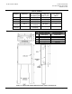
Door Layout
NOTE: Controls cannot be mounted to the door of the flush mount cabinet.
Perform the following steps when preparing to lay out a cabinet door:
1. Determine controls to be mounted on the door.
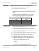
2. Determine if the controls mounted in the door will clear the mounting plate when
tubing or wires are attached. See Figure 3 and Table 5 for dimensions. Table 4
provides the approximate space requirements for controls frequently mounted in
the door.
3. Determine if the total weight of the controls (see Table 4) to be mounted on the
door are within the maximum weight limitations shown in Table 3. If weight
limitations are exceeded, the door might sag and prevent proper closure.
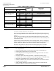
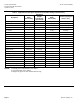
Table 4. Weight Limitations.
Cabinet
Size
Maximum Weight of Controls
That Can Be Mounted on Door
lb (Kg)
Maximum Number of Selector
Switches That Can Be Mounted
on Door
Size 1 21 (9.5) 14
Size 2 24 (11) 16
Size 3 30 (14) 20
Size 4 93 (42) 62
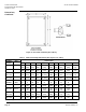
Cabinet Installation
(Non-flush mount)
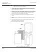
1. There are four keyhole mounting holes in the back surface of the cabinet. Their
sizes and locations are shown in Figure 5. Use wall anchors that are suitable to
support the weight of the cabinet and its contents.
2. If more than one cabinet is to be mounted in the same location, allow at least
2 inches (51 mm) between cabinets to provide space for doors to open properly.
3. The cabinets are symmetrical before cutouts have been made, so the door can be
mounted with the hinge on the left or right side.
4. Determine the size of the knockouts required for the number and size of pneumatic
tubes and wires to be brought into the cabinet.
5. If more than one knockout is required, divide the tubes and wires for easy
connection to the controls.
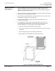
6. If a cabinet light is required, order per instructions under accessories. The
recommended mini work light has a 2-inch diameter by 4-inch long (51 mm ×
102 mm) bulb holder on a 15-inch (381 mm) long flexible metal arm.
a. Remove the plug and mounting bracket from the light.
b. Punch out the 7/16-inch (11 mm) diameter knockout in the center of the top of
the cabinet.
c. Attach the light using the nut and washer provided with it.
d. Wire the light cord in compliance with local electrical codes.