
Data Sheet for Product
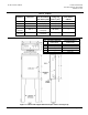

Technical Instructions CP 567 Control Cabinets
Document Number 155-272P25
October 12, 2017
Page 8 Siemens Industry, Inc.
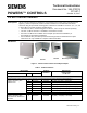
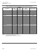
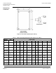
Table 5. Approximate Panel Space Requirements (Includes Fitting and Clearances).
Equipment
Door Moun
ting
Depth
Inches (mm)
Equipment
Weight
Pounds (kg)
(See Note 3)
Mounting Plate
Depth
Inches (mm)
Inside Area Required
Inches
2
(cm
2
)
6 Input Sig. Selector – – 4 (102) 12 (77)
656 Pilot Valve – – 3 (76) 100 (645)
ARG61.00 Wall Mount Case – – 8.52 (216.4) 13.10 (84.5)
ARG61.01 Panel Mount Case 7.52 (191) 1.65 (0.750) – 11.28 (72.8)
D.P. Switch – – 3 (76) 45 (290)
Diff. Press. Reg. – – 3 (76) 35 (226) (See Note 1)
E.P. – – 1-1/4 (32) 30 (194)
Electric Relay – – 4 (102) 30 (194)
Enthalpy Comparator – – 3-1/2 (89) 30 (194)
FZA 21 Remote Setting Unit 0.87 (22) 0.11 (0.05) – 1.98 (12.76)
FZA 61 Remote Setting Unit 1.10 (28) 0.15 (0.07) – 3.00 (19.36)
Gauges 1-1/2" 2 (51) 0.2 (0.09) 1-1/2 (38) 4 (26) (See Note 2)
Gauges 2-1/2" 2-1/2 (64) 0.5 (0.22) – –
Gauges 3-1/2" 2-1/2 (64) 0.6 (0.27) – –
Min (PRV) 3 (76) 0.5 (0.22) 2 (51) 10 (65)
MP, BR, Analog Relays 4-1/2 (114) 2 (0.91) 2-1/2 or 5 (64 or 127) 42 (271)
P.E. (Single) – – 3-1/2 (89) 28 (181)
Positioning/Selector Switch 3 (76) 2 (0.91) 5 (127) 10 (65) (See Note 2)
PRV (Powers) – – 5-1/2 (140) 100 (645)
RC 195 – – 3-1/2 (89) 6 0(387)
Static Pressure Reg. – – 4 (102) 30 (194)
Switching Relay – – 2-1/2 (64) 65 (419)
NOTES: 1. Normally not mounted inside of the cabinet.
2. If mounted inside of the cabinet.
3. Weights are given for door mounted devices only.