4 847 2-port valves VVP47..(S) 3-port valves VXP47.. 3-port valves with bypass VMP47..(S) Acvatix™ 2-port and 3-port terminal unit valves PN16 VVP47..(S) VXP47.. VMP47..(S) • Bronze valve body CC491K (Rg5) max. 4% Pb • DN 10, DN 15 and DN 20 • kvs 0.25 to 4 m3/h • Linear characteristic • Flat seal male threaded connections G..B to ISO 228-1 • V..P47..S valves: Male threaded connections for use with Conex compression fittings for copper pipes • Manual adjuster • Can be combined with SSP.., SFP..
Use Type summary • For use in ventilation and air conditioning systems for water-side terminal unit control in closed circuits, e.g. for induction units, fan coil units, small re-heaters and small recoolers. − 2-pipe systems with 1 heat exchanger for heating and cooling − 4-pipe systems with 2 separate heat exchangers for heating and cooling • In closed-circuit zone heating systems, e.g. for: − Separate floors in a building − Apartments and individual rooms • The VXP47..S 3-port valves together with SFP..
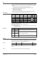
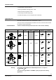
Equipment combinations Valves Electromotoric Electrothermal actuators actuators SSP.. VVP47.10-0.25…0.4 VVP47.10-0.63…1(S) VVP47.10-1.6(S) VVP47.15-2.5(S) VVP47.20-4 VXP47.10-0.25…0.4 VXP47.10-0.63…1 VXP47.10-1.6 VXP47.15-2.5 VXP47.20-4 VMP47.10-0.25…0.4 VMP47.10-0.63…1(S) VMP47.10-1.6(S) VMP47.15-2.5(S) Data sheet SFP.. STP..3..
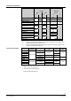
Sizing (A k vs → AB ) 4.0 2.5 1.6 1.0 3 0.6 3 0.4 1 5 0.2 2 Example: 1 2 3 V 100 = 0.083 l/s ∆pv100 = 9 kPa Required kvs-value = 1.
Mechanical design • Combined disc / plug flow restrictor • Seat ring embedded in through-port A AB • Seat machined into bypass B AB. • Continuously lubricated sealing rings • Conical return springs, for more compact valve construction Engineering notes Also refer to "Mounting notes" and "Commissioning", page 7. The 2-port valves should preferably be installed in the return, where the stem seal will be exposed to lower temperatures. A strainer should be fitted upstream of the valve.
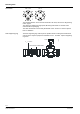
Mounting notes Orientation SSP.., SFP.. STP..3.. 90° 4362Z01 90° 90° 90° 90° 90° 2185Z12 The specified direction of flow must be observed in all cases, also refer to "Engineering notes", page 5. The valves are delivered in single packs; Mounting Instructions 74 319 0301 0 are enclosed with the packaging. The valve and actuator can be easily assembled on site. There is no need for special tools or calibration. The AL50 supporting ring must be put into position before mounting the actuator SFP..
Commissioning Commission the valve only if the manual knob or actuator have been mounted correctly. Manual adjustment The straight-through control path A → AB can be opened either electrically via the actuator, or by adjustment with the manual button. In the case of 3-port valves, this throttles or closes bypass B. Maintenance V..P47..(S) valves require no maintenance.
Technical data Operating data PN class PN 16 to EN 1333 Permissible operating pressure 1600 kPa (16 bar) Valve characteristic Path A → AB Bypass B → AB linear linear Leakage rate Path A → AB Bypass B → AB Permissible media Standards, directives and approvals Environmental compatibility to DIN EN 1349 0…0.05 % of kvs value 0…0.
Materials Dimensions / weight Accessories Valve body bronze CC491K (Rg5) max. 4% Pb Stem stainless steel Plug, seat ring, gland brass Stem seal EPDM O-rings Dimensions refer to "Dimensions", page 10 Threaded connections (V..P47..) Valve Threaded fittings G..B to ISO 228-1 R/Rp.. to ISO 7-1, G.. to ISO 228-1 Threaded connections (V..P47..S) Valve DN 10 Valve DN 15 G..B to ISO 228-1 W1⅛-14 to BS84 Actuator connection M30 x 1.5 Weight refer to "Dimensions", page 10 ALG..2, ALG..
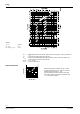
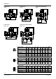
Dimensions 3-port valves VXP47.. H1 G H2 4847Z08 H2 d G H1 H2 K L3 L3 d G H1 4847Z06 4847Z07 VVP47.. 3-port valves with bypass VMP47.. d 2-port valves L2 L1 L2 L1 L2 L1 2-port valves 3-port valves with T-bypass VMP47..(S) H2 d G H1 H2 K L3 d G H1 4850Z03 4850Z01 VVP47..(S) L2 L1 L2 L1 AB A AB A B A B AB Product number DN d [mm] 10.5 H1 [mm] 46 H2 [mm] 10 G [Inch] G½B ≈ 49 L1 [mm] 60 L2 [mm] 30 L3 [mm] 19 Weight [kg] 0.32 VVP47.10-0.25…1.6 VVP47.
Sets of threaded fittings with flat seal: Set of 2 (for V..P47..) R G 4847Z09 Prod. no. /stock no. Prod. No. Stock no. T Connection pipe side G Rp [Inch] [Inch] ALG132 External thread G ½ R⅜ ALG142 External thread G ¾ R½ ALG122 Internal thread G¾ Rp ⅜ ALG152 ALG152B S55846-Z100 Internal thread G1 Rp ½ G Rp [Inch] [Inch] G Rp 4363M02 L Set of 3 (for V..P47..) R G 4847Z09 Prod. no. /stock no. Prod. No. Stock no.
Overview fitting combinations (with V..P47..) ALG... type for valve type DN ALG132 VVP47.10-0.25...1.6 ALG133 VXP47.10-0.25...1.6 2 x ALG132 VMP47.10-0.25...1.6 ALG142 VVP47.15-2.5 ALG143 VXP47.15-2.5 2 x ALG142 VMP47.15-2.5 ALG152 R Rp L T [inch] [inch] [inch] [mm] [mm] 10 G½ R⅜ ≈ 24 ≈9 15 G¾ R½ ≈ 29.5 ≈ 12 20 G1 ≈ 23 ≈ 13 VVP47.20-4 ALG152B ALG153 G VXP47.
Spare parts Type Stock No. S55845-Z182 1) S55845-Z182 1) Description ALQ1 Protecting Cap M30x1.5 Number 10 Multipack of 10 pieces Revision numbers Product number VVP47.. 1) Valid from manufacturing date 0809 1) Product number VXP47.. Valid from manufacturing date 0809 1) Product number VMP47..
Issued by: Siemens Switzerland Ltd Smart Infrastructure Global Headquarters Theilerstrasse 1a CH-6300 Zug Switzerland Tel. +41 58 724-2424 www.siemens.com/buildingtechnologies © Siemens Switzerland Ltd, 2009 Technical specifications and availability subject to change without notice.