Cerberus® CS1140 Gateway CK1142 Interface Description SW Ver. 5.1x Application for: Standard Copy no.
Data and design subject to change without notice. / Supply subject to availability. © Copyright by Siemens Building Technologies AG We reserve all rights in this document and in the subject thereof.
Changes in the documentation ......................................................................... 3 1 Overview ................................................................................................... 4 2 CS11 Hardware architecture ................................................................... 4 3 CS11 Information architecture................................................................ 5 3.1 Logical tree.................................................................................
5.8.5 Structure 1562 (attr = RTFIRE): ALARM remote transmission channel element.....................................................................................................53 5.8.6 Structure 1562 (attr = RTFAULT): FAULT remote transmission channel element.....................................................................................................54 5.8.7 Structure 1562 (attr = RTOTHER): OTHER remote transmission channel element.................................................................
Changes in the documentation Errors in document e1560 V4.4x The page numbers refer to the respective document. Page Correction 9 paragraph SECTION, the system limit is 255 sections per CC11 80 Structure 1562/RTOTHER, valid states, no command applicable except ACKNOWLEDGE FAULT. Changes since document e1560 V4.4x Topic Comments Hierarchical level FUNCTION UNIT Structures 1392/1393 New structures 1392/1393 VDS-INTERFACE (used only in Germany).
1 Overview The AlgoRex CS11 fire detection system represents the latest generation of the CERBERUS fire detection technology. This system offers the following features: - High detection intelligence. - Excellent communications capability - High configuration flexibility - High system availability CS11 systems can be integrated into a DMS7000 network via a gateway and thus connected to a CERBERUS monitoring system or an external system.
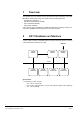
3 CS11 Information architecture The information within the CS 11 system is arranged hierarchically. The logical/geographical structure is represented by the logical tree, the physical (hardware) structure by the physical tree. These two trees are interconnected. Tree structure Area Section parent child Zone Element Device Function unit child parent Station PhysicalTree 5 Fire & Security Products Siemens Building Technologies Group 1964_a_en_--.doc 07.
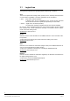
3.1 Logical tree The logical tree represents the logical/geographical data image of a station. Area The Area comprises lower ranking nodes (sections, zones, elements) that are linked to a common alarm organization. The alarm organization can be set either to: DAY (Day mode, manned operation) A danger event can be investigated by the on-site security personnel before external intervention squads (fire department) are summoned.
3.2 Physical tree The physical tree represents the installed hardware components of a station. Station The term Station refers to individual nodes on the C-Bus. Stations supply primarily information on faults in the connected hardware. Currently the following stations exist: CC11, CT11 and CK11. System limit: 16 stations per CS11. Function unit The term function unit refers to modules connected to the internal I-bus of the stations.
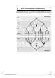
4 Integration of the CS11 architecture into the DMS7000 A CS11 system can be integrated into a DMS7000 network via a CK11 gateway. Due to the dissimilarity of the systems special measures must be taken. 4.1 Basis for integration The telegram functionality of the CS11 is oriented toward the CS10 fire detection system. Existing telegrams are re-used as far as possible.
Addressing of the CS11 stations The ADF1 field contains a fixed number of “00”. The ADF2 field contains an assigned, two-digit value that corresponds to the purpose of the datapoint. DMS7000 network addresses As the sequence numbers (SeqNr) are unique only within the corresponding CC11 station, additional measures must be taken to ensure the CS11-wide uniqueness of the datapoint address. This is accomplished by assigning a separate DMS7000 network address per CC11 station.
4.3.2 Syntax EBNF symbols: . End of sentence “x” Terminal symbol {} 0..n repetitions [] optional part () precedence | exclusive OR ‘ ‘ descriptive definition Common: file = Record{Record}. Record = Field{“;”Field”} Newline. Field = “““Text”””. Newline = ‘Line Delimiter (e.g. DOS: )’. Syntax description: Configfile = Record { Record }. Record = RecordNr “;” (Record1 | Record2) Newline. RecordNr = DecNumber.
4.3.3 Semantics The semantics describe the valid contents and significance of the fields within the configuration file. RecordNr This field contains the line number of the entry in the configuration file. RecordType This field contains the type of entry.
DMSAdf12 This field contains the ADF1/2 number which is derived from the SeqNr. From the viewpoint of the DMS7000 the ADV1/2 number is the address of the CC11 datapoint. This number is the primary key for assigning process information (telegrams) to structure information (configuration file). Attribute This field contains StrucNr-dependent specifics. If no specifics are needed this field contains a dash (“-”).
4.4 Information depth The information depth of the individual datapoints is determined by the (limited) functionality of the DMS7000 network. Parallel information must be mapped to unique states or to separate datapoints. No differentiation between the subtypes within the same hierarchical levels ZONE, ELEMENT and IBD. Example: Single detector zone and multi-detector zone are both detector zones within the DMS7000. States that are too detailed are summarized in a collective state (example: Faults).
5 CS11 Behavior in the DMS7000 5.1 Description of the data structures The same description scheme is used for each data structure: - Quick-reference description - Valid states - State transition diagram - Telegram repertoire In order to make the structure description identifiable also across several pages, the corresponding structure number is shown in front of the headings.
5.1.4 Telegram repertoire Table that represents the telegram repertoire for MESSAGES and COMMANDS The Priority field in the MESSAGES table shows the classification of the corresponding messages based on the following scale: - NORMAL (low priority) - ANOMALY - FAULT - ALARM (high priority) Based on the priority also the acknowledgment command telegram can be determined. The Text A and Text B fields contain the standard texts introduced in the DMS7000 network.
5.2 Hierarchical level: AREA 5.2.1 Structure 1801: FIRE area Abstract representation of a FIRE area. The area contains the datapoints: - ORGANIZATION - GENERAL ALARM - ALARM RT DELAY (RT = Remote transmission) - PART OF SYSTEM OFF - FAULT - RT-DEVICE (datapoint formerly presented in structure 1563) Datapoint ORGANIZATION (ORG) This datapoint relates to the alarm organization (CAC) within the area.
Datapoint ALARM (ALM) This datapoint contains the alarm level of the corresponding area. 1801/ALM: Addressing Sector: FIRE ADF1/2: aaCD (aa = “A” + , example: A2CD = alarm in area 2) 1801/ALM: Valid states State Description RESET The area is not in the alarm state. Valid commands LOCAL ALARM Cause: ACKNOWLEDGE In Day mode an alarm of an automatic detector has been detected. RESET GENERAL ALARM Cause: In Day mode an alarm triggered by a manual callpoint has been detected.
Datapoint: ALARM RT DELAY (ARD) This datapoint represents the state of the “Alarm Remote Transmission Delay” within the area. If the Alarm Remote Transmission Delay is switched off while an alarm event with RT requirements is pending, the current monitoring times are bypassed and the remote transmission is activated immediately.
Datapoint: PART OF SYSTEM OFF (PSO) This datapoint becomes active when one or more parts of the system have been switched off in the corresponding area. 1801/PSO: Addressing Sector: FIRE ADF1/2: aaEC (aa = “A” + , example: A4EC = Datapoint ‘Part of system Off’ in area 4) 1801/PSO: Valid states State Description Valid commands INACTIVE No system parts are switched off in the corresponding area. --- ACTIVE Parts of the system are switched off in the corresponding area.
Datapoint: FAULT (FLT) This datapoint becomes active if one or several faults exist in the corresponding area. 1801/FLT: Addressing Sector: FIRE ADF1/2: aaED (aa = “A” + , example: A1ED = datapoint ‘Fault’ in area 1) 1801/FLT: Valid states State Description Valid commands INACTIVE No faults exist in the corresponding area. --- ACTIVE Faults exist in the corresponding area.
Datapoint: RT-DEVICE (RTD) This datapoint reflects the current state of the remote transmission device associated to this area. 1801/RTD: Addressing Sector: FIRE ADF1/2: aaEA (aa = “A” + , example: A2EA = datapoint ‘RT-Device’ in area 2) 1801/RTD: Valid states State Description INACTIVE The affiliated remote transmission device is in the quiescent state. Valid commands DISABLED The affiliated remote transmission devices is unable to transmit the ACKNOWLEDGE requested message.
5.3 Hierarchical level: SECTION (detection) The hierarchical level SECTION basically summarizes the states of the affiliated zones. In special cases (example: extinguishing section) additional, section-specific datapoints exist. 5.3.1 Structure 1701: FIRE Section The FIRE section has no own functionality but contains collective information of the affiliated detection zones. With respect to the DMS7000 network the ALARM datapoint is made available as an non-acknowledgeable summary alarm.
1701: Telegram repertoire COMMANDS (ZONE commands from SECTION level) It is valid to use selected ZONE level commands on SECTION level. The command is then propagated to ALL zones belonging to the respective section.
1702/EAL: State transition diagram To EXTING. ALRM MAN. ACTIVATION EXTING. ALARM AUTOM. DETECTOR EXTING. ALARM MAN. DETECTOR EXTING. ALARM MAN. RELEASE --- --- --- Extinguishing alarm ----------------N 08 85 EXTING. ALARM AUTOM. DETECTOR --- --- --- Extinguishing alarm ----------------N 08 85 EXTING. ALARM MAN.
Datapoint RELEASE (REL) This datapoint contains the state of the extinguishing release system. 1702/REL: Addressing Sector: EXTINGUISHING ADF1/2: bbAE (bb = “B” + , example: B8AE = Release in section 8) 1702/REL: Valid states State Description Valid commands ENABLED The activation of the extinguishing system (if alarm criteria are DISABLE met) is enabled. DISABLE AUTOM. RELEASE AUTOM. RELEASE DISABLED The extinguishant release by automatic detectors is inhibited.
1702: Telegram repertoire COMMANDS (ZONE commands from SECTION level) It is valid to use selected ZONE level commands on SECTION level. The command is then propagated to ALL zones belonging to the respective section.
5.4 Hierarchical level: SECTION (control) The hierarchical level SECTION basically summarizes the states of the affiliated control zones. 5.4.1 Structure 1751: Control Section Abstract representation of a CS11 control section. The control section does not provide DMS7000-relevant data. 5.5 Hierarchical level: ZONE (Detection) The CSX detection level ZONE is responsible for the alarm decision based on the information supplied by the affiliated elements and the parameterized decision criteria.
1601: State transition diagram To WARNING ALARM OFF TEST REVISION WARNING --- Alarm ---------------N 03 3B U 01 01 Off -------------N 03 3B Q 64 56 Test -------------N 03 3B Q 64 57 ALARM --- --- Off -------------N 01 85 Q 64 56 Test -------------N 01 85 Q 64 57 OFF --- --- --- Test -------------Q 64 57 --- TEST --- --- Off -------------Q 64 56 --- REVISION WARNING ----------------U 03 3A Alarm ---------------U 01 01 Off -------------Q 64 56 RENOVATION WARNING ---------------
5.5.2 Structure 1602: Multi-Logic zone FIRE sector (A) In a multi-logic zone the alarm decision is based on the response of multiple detection devices affiliated with the zone. The conditions can be parameterized within the CC11. 1602/A: Sector: ADF1/2: Addressing FIRE Based on sequence number 1602/A: Valid states State Description NORMAL The zone is in the ON state. Incoming danger levels are processed.
1602a: State transition diagram To WARNING ALARM OFF TEST REVISION WARNING --- Alarm ---------------N 03 3B U 01 01 Off -------------N 03 3B Q 64 56 Test -------------N 03 3B Q 64 57 ALARM --- --- Off -------------N 01 85 Q 64 56 Test -------------N 01 85 Q 64 57 OFF --- --- --- Test -------------Q 64 57 --- TEST --- --- Off -------------Q 64 56 --- REVISION WARNING ----------------U 03 3A Alarm ---------------U 01 01 Off -------------Q 64 56 RENOVATION WARNING --------------
5.5.3 Structure 1602: Multi-Logic zone EXTINGUISHING sector (B) In a multi-logic zone the alarm decision is based on the response of several detection devices affiliated with the zone. The conditions can be parameterized within the CC11. 1602/B: Sector: ADF1/2: Addressing EXTINGUISHING Based on sequence number 1602/B: Valid states State Description Valid commands NORMAL The zone is in the ON state. Incoming danger levels are processed.
1602/B: State transition diagram To WARNING PRE-ALARM EXTINGUISHING ALARM OFF TEST REVISION RENOVATION NOT READY NORMAL WARNING --- Pre-alarm ---------------N 03 3B U 04 01 --- Off -------------N 03 3B Q 64 56 Test -------------N 03 3B Q 64 57 Warn. & mode = Rev ---------------N 03 3B N 64 3F Warn.
1602/B: Telegram repertoire MESSAGES Sector DMS Adr ADF1/2 Sep Data A Data B L U/Q 03 3A Priority Text A Text B ANOMALY Warning --- L N 03 3B NORMAL Warning End L U/Q 04 01 ALARM Pre-alarm Autom. detector L N 04 85 NORMAL Pre-alarm Reset L U/Q 08 01 ALARM Extinguishing alarm Autom.
5.5.4 Structure 1605: Manual callpoint zone In a manual callpoint zone only one detection device assigned to the zone needs to respond in order to reach the ALARM state. 1605: Sector: ADF1/2: Addressing FIRE Based on sequence number 1605: Valid states State Description NORMAL The zone is in the ON state. Incoming danger levels are processed. OFF TEST Valid commands ALARM An affiliated detection device has reached danger level 3 (alarm).
1605: Telegram repertoire: COMMANDS Sector DMS Adr ADF1/2 Sep Data A Data B Text A Text B W R 01 80 Alarm Acknowledgment (Alarm) W R 01 83 Alarm Reset W R 64 55 Zone On W R 64 56 Zone Off W R 64 57 Zone Test 5.5.5 Structure 1610: Digital zone Digital zones process binary information rather than danger levels.
1610: Telegram repertoire MESSAGES Sector DMS Adr ADF1/2 Sep Data A Data B Priority Text A Text B LP U/Q 01 01 ALARM Alarm Autom.
1651: Telegram repertoire MESSAGES Sector DMS Adr ADF1/2 Sep Data A Data B Priority Text A Text B P U/Q 62 46 FAULT Control zone Faulty P N 62 4D NORMAL Control zone Inactive P Q 62 56 ANOMALY Control zone Off 1651: Telegram repertoire COMMANDS Sector DMS Adr ADF1/2 Sep Data A Data B Text A Text B P R 62 55 Control zone On P R 62 56 Control zone Off P
5.7 Hierarchical level: ELEMENT (detection) The detection devices evaluate the information supplied by detectors (danger levels) and digital inputs, and transmit the results to the higher ranking zones. 5.7.
1501: Telegram repertoire MESSAGES Sector DMS Adr ADF1/2 Sep Data A Data B WL Q 67 0B Priority Text A Text B ANOMALY Detection device Test alarm WL N 67 3C NORMAL Detection device Normal WL U/Q 67 46 FAULT Detection device Faulty WL U/Q 67 48 ANOMALY Detection device Drift WL Q 67 4F ANOMALY Detection device Active WL Q 67 56 ANOMALY Detection dev
5.7.2 Structure 1502: Interactive manual callpoint element Abstract representation of an interactive series DS11-I manual callpoint. 1502: Addressing Sector: FIRE ADF1/2: Based on sequence number 1502: Valid states State NORMAL Description The element is in the ON state (connected to the circuit). Incoming danger levels are transmitted to the higher ranking zone. The affiliated detector has reached a danger level > 1.
5.7.3 Structure 1503: Collective manual callpoint element Abstract representation of a collective series DS11-C manual callpoint. 1503: Sector: ADF1/2: Addressing FIRE Based on sequence number 1503: Valid states State Description NORMAL The element is in the ON state (connected to the circuit). Incoming OFF danger levels are transmitted to the higher ranking zone. Valid commands ACTIVE The affiliated detector has reached a danger level > 1.
5.7.4 Structure 1508: AnalogPlus element Abstract representation of a series DS11-A (AnalogPlus) detector. 1508: Addressing Sector: FIRE or EXTINGUISHING ADF1/2: Based on sequence number 1508: Valid states State Description Valid commands NORMAL The element is in the ON state (connected to the circuit). Incoming danger levels are transmitted to the higher ranking zone. OFF ACTIVE The affiliated detector has reached a danger level > 1.
5.7.5 Structure 1510...1512: Collective line element Abstract representation of a series DS11-C collective line. Elements 1510 .. 1512 have different internal characteristics (pulse memory, delays), however, these do not appear on the DMS7000 side. 1510: Addressing Sector: FIRE or EXTINGUISHING ADF1/2: Based on sequence number 1510: Valid states State Description Valid commands NORMAL The element is in the ON state (connected to the circuit).
5.7.6 Structure 1520: Digital detection device Abstract representation of digital transmitters (contacts, etc.) whose binary states are translated into danger levels: Log. 0 = Danger level 0 Log. 1 = Danger level 3 1520: Sector: ADF1/2: Addressing FIRE Based on sequence number 1520: Valid states State Description Valid commands NORMAL The element is in the ON state (connected into the circuit). Incoming danger levels are transmitted to the higher ranking zone.
5.7.7 Structure 1521: Digital manual callpoint element Abstract representation of digital transmitters (contacts, etc.) whose binary states are translated into danger levels and which are used as manual callpoints: Log. 0 = Danger level 0 Log. 1 = Danger level 3 1521: Sector: ADF1/2: Addressing FIRE Based on sequence number 1521: Valid states State Description Valid commands NORMAL The element is in the ON state (connected into the circuit).
1521: Telegram repertoire MESSAGES Sector DMS Adr ADF1/2 Sep Data A Data B Priority Text A Text B W Q 67 0B ANOMALY Detection device Test alarm W N 67 3C NORMAL Detection device Normal W U/Q 67 46 FAULT Detection device Faulty W Q 67 4F ANOMALY Detection device Active W Q 67 56 ANOMALY Detection device Off W U/Q 67 5F FAULT Detection device Not r
5.7.8 Structure 1525: Digital element Abstract representation of digital transmitters (contact, etc.) 1525: Sector: ADF1/2: Addressing EXTINGUISHING or PLANT MONITORING Based on sequence number 1525: Valid states State Description Valid commands NORMAL The element is in the ON state (connected into the circuit). Incoming danger levels are transmitted to the higher ranking zone. OFF ACTIVE The affiliated transmitter signals Log.
5.8 Hierarchical level: ELEMENT (controls) Control devices receive control commands from higher ranking instances and transmit these to the physical devices. 5.8.1 Structure 1551: Output element without feedback Abstract representation of a digital output. Activation of the peripheral devices is not monitored.
5.8.2 Structure 1552: Output element with feedback Abstract representation of a digital output. Activation of the peripheral device is monitored via a separate digital input. 1552: Addressing Sector: PLANT MONITORING ADF1/2: Based on sequence number 1552: Valid states State Description Valid commands INACTIVE The element is in the ON state (connected into the circuit). The affiliated digital output is in the quiescent state.
5.8.3 Structure 1560: Internal horn element Abstract representation of an internal horn output. Internal horn elements receive their control commands directly from the higher ranking AREA. Typically the internal horn is activated simultaneously with the buzzer on the CT11. 1560: Sector: ADF1/2: Addressing FIRE Based on sequence number 1560: Valid states State Description Valid commands INACTIVE The element is in the ON state (connected into the circuit).
5.8.4 Structure 1561: External horn element Abstract representation of an external horn output. External horn elements receive their commands directly from the higher ranking AREA. Typically the external horn is activated in accordance with the Cerberus Alarm Concept (CAC) after expiration of the presence monitoring time V1 or alarm investigation time V2.
1561: State transition diagram ACTIVE OFF FAULTY INACTIVE ACTIVE --- Off -------------Q 73 56 Active & Faulty -------------U 73 46 Inactive -------------N 73 4D OFF --- --- On & Faulty -------------U 73 46 On -------------N 73 4D FAULTY --- Off -------------Q 73 56 --- Faulty ------------N 73 4D Active -------------U 73 4F Off -------------Q 73 56 Faulty -------------U 73 46 --- To From INACTIVE 1561: Telegram repertoire: MESSAGES Sector DMS Adr ADF1/2 Sep Data A Data B Priori
5.8.5 Structure 1562 (attr = RTFIRE): ALARM remote transmission channel element Abstract representation of a remote transmission output for ALARMS. Remote transmission channels receive their control commands directly from the higher ranking AREA. Typically it is activated in accordance with the CERBERUS Alarm Concept (CAC), after expiration of the presence monitoring time V1 or alarm investigation time V2.
5.8.6 Structure 1562 (attr = RTFAULT): FAULT remote transmission channel element Abstract representation of a remote transmission output for FAULTS. Remote transmission channels receive their control commands directly from the higher ranking AREA. Typically it is activated in accordance with the CERBERUS Alarm Concept (CAC), after expiration of the presence monitoring time V1.
5.8.7 Structure 1562 (attr = RTOTHER): OTHER remote transmission channel element Abstract representation of a remote transmission output for OTHER (selectable) events. Remote transmission channels receive their control commands directly from the higher ranking AREA. Typically it is activated in accordance with the CERBERUS Alarm Concept (CAC), after expiration of the presence monitoring time V1.
5.8.8 Structure 1563: Remote transmission device element DOES NOT EXIST ANYMORE. The information content found in structure 1801. 5.8.9 Structure 1564: of structure 1563 can be Alarmhorn (under area CAC control) Abstract representation of an alarmhorn whose activation / deactivation is controlled by the area CAC. The behavior is identical to structure 1561 (External horn). 5.8.
1301/ALM: Telegram repertoire MESSAGES Sector DMS Adr ADF1/2 Sep Data A Data B Priority Text A Text B W U/Q 01 00 ALARM Alarm --- W N 01 85 NORMAL Alarm Reset 1301/ALM: Telegram repertoire COMMANDS Sector DMS Adr ADF1/2 Sep Data A Data B Text A Text B W R 01 80 Alarm Acknowledgment (Alarm) W R 01 83 Alarm Reset Datapoint FAULT (FLT) 1301/FLT: Addressing Sector: BASIC ADF1/2: Based on sequen
5.9.2 Structure 1302: Function unit MS9I Line Abstract representation of an MS9I line. The function unit contains the two datapoints ALARM and FAULT. The datapoints appear under the same ADF1/2 address, but with different sector ID. Together this results in a unique datapoint address. Datapoint ALARM (ALM) 1302/ALM: Addressing Sector: FIRE ADF1/2: Based on sequence number 1302/ALM: Valid states State Description Valid commands RESET The function unit is not in the alarm state.
Datapoint FAULT 1302/FLT: Addressing Sector: BASIC ADF1/2: Based on sequence number 1302/FLT: Valid states State Description NORMAL No fault in the function unit.
5.9.3 Structure 1303: Function unit DS11-A Line Abstract representation of an DS11-A (AnalogPlus). The function unit contains the two datapoints ALARM and FAULT. The datapoints appear under the same ADF1/2 address, but with different sector ID. Together this results in a unique datapoint address. Datapoint ALARM (ALM) 1303/ALM: Addressing Sector: FIRE ADF1/2: Based on sequence number 1303/ALM: Valid states State Description Valid commands RESET The function unit is not in the alarm state.
Datapoint FAULT (FLT) 1303/FLT: Addressing Sector: BASIC ADF1/2: Based on sequence number 1303/FLT: Valid states State Description NORMAL No fault in the function unit.
5.9.4 Structure 1310: Function unit DS11-C line Abstract representation of a DS11-C (collective) line. 1310: Addressing Sector: BASIC ADF1/2: Based on sequence number 1310: Valid states State Description NORMAL No fault in the function unit.
5.9.5 Structure 1320: Function unit Digital I/O interface Abstract representation of a digital I/O module. 1320: Addressing Sector: BASIC ADF1/2: Based on sequence number 1320: Valid states State Description Valid commands NORMAL No fault in the function unit.
5.9.6 Structure 1340: Function unit Supply monitoring Abstract representation of a power supply monitoring module. 1340: Sector: ADF1/2: Addressing BASIC Based on sequence number 1340: Valid states State Description NORMAL No fault in the function unit.
5.9.7 Structure 1390: Function unit display panel (CI11 only) Abstract representation of a CI11 display panel. This structure is only visible in CI11 control panels. 1390: Sector: ADF1/2: Addressing BASIC Based on sequence number 1390: Valid states State Description NORMAL No fault in the function unit.
5.9.8 Structure 1391: Function unit FBA panel (CI11 only) Abstract representation of a FBA panel (fire brigade control panel). This structure is only visible in CI11 control panels. 1391: Sector: ADF1/2: Addressing BASIC Based on sequence number 1391: Valid states State Description NORMAL No fault in the function unit.
5.9.9 Structure 1392: CC11 VDS Interface Part 1 Datapoint: VDS_FBF (FBF) This datapoint covers the fault signals of the FBF (fire brigade operating panel) and the basic function unit. 1392/FBF: Addressing Sector: BASIC ADF1/2: sequence number based 1392/FBF: Valid states State Description Valid commands NORMAL No faults in the FBF or function unit.
Datapoint: VDS_FUE (FUE) This datapoint covers the state of the alarm remote transmission (FUE). 1392/FUE: Addressing Sector: FIRE ADF1/2: sequence number based 1392/FUE: Valid states State Description INACTIVE The remote transmission (FUE) is ready and in the quiescent state. Valid commands ACTIVE The FUE is activated. OFF The FUE is switched-off.
5.9.10 Structure 1393: CC11 VDS Interface Part 2 Datapoint: VDS_LSE (LSE) This datapoint covers the states of the extinguishing interface (LSE). 1393/LSE: Addressing Sector: EXTINGUISHING ADF1/2: sequence number based 1393/LSE: Valid states State Description ENABLED The extinguishing system (LSE) is ready and in the quiescent state. Valid commands ALARM The LSE is activated. ACKNOWLEDGE RESET DISABLED The LSE is disabled.
Datapoint: VDS_FSK (FSK) This datapoint covers the states of the fire brigade key (FSK). 1393/FSK: Addressing Sector: FIRE ADF1/2: sequence number based 1393/FSK: Valid states State Description NORMAL The key box (FSK) is ready and in the quiescent state. Valid commands SABOTAGE The FSK is tampered.
1393/FSK: Telegram repertoire MESSAGES Sector DMS Adr ADF1/2 Sep Data A Data B Priority Text A Text B W U/Q 0C 00 ALARM Sabotage --- W N 0C 85 ALARM Sabotage Reset W U/Q 34 46 FAULT Function unit Faulty W U/Q 34 25 ANOMALY Function unit FSK manually unlocked W U/Q 34 26 ANOMALY Function unit FSK unlocked W U/Q 34 27 ANOMALY Function unit FSK open
5.9.12 Structure 1396: Function unit LON interface part 1 Abstract representation of a LON network with attached nodes 1..10. 1396: Sector: ADF1/2: Addressing BASIC Based on sequence number 1396: Valid states State Description NORMAL No fault in the function unit.
5.9.13 Structure 1397: Function unit LON interface part 2 Abstract representation of a LON network with attached nodes 11..32. 1397: Sector: ADF1/2: Addressing BASIC Based on sequence number 1397: Valid states State Description NORMAL No fault in the function unit.
5.10 Hierarchical level: STATION The following devices are Stations on the C-bus: - CC11Control units - CI11 Compact control units (CC11 and CT11 integrated on the same hardware) - CT11 Display terminals - CK11 DMS7000 Gateway Stations contain parallel information that cannot be combined into a unique state. For this reason the information is mapped to several datapoints. 5.10.1 Structure 1201: CC11 Control unit Abstract representation of a CC11 control unit.
Datapoint CONTROL UNIT (CTP) 1201/CTP: Addressing Sector: BASIC ADF1/2: 0003 1201/CTP: Valid states State Description NORMAL No fault exists in the station Valid commands FAULTY One of the following faults exists in the station: - Emergency operation monitoring defective - C-Bus fault - I-Bus fault - Configuration error ACKNOWLEDGE 1201/CTP: State transition diagram FAULTY NORMAL FAULTY --- Fault -------------N 33 3C NORMAL Fault -------------U 33 46 --- To From 1201/CTP: Telegram repertoir
Datapoint PRINTER (PRT) 1201/PRT: Addressing Sector: BASIC ADF1/2: 000D 1201/PRT: Valid states State Description NORMAL The printer is switched on and there is no fault. OFF The printer is switched off. FAULTY Valid commands One of the following faults exists in the printer: ACKNOWLEDGE - XOFF or DTR Timeout - End of paper - Printing mechanism blocked.
5.10.
5.10.3 Structure 1203: CK11 Gateway Abstract representation of a CK11 gateway. The station contains the datapoints: - POWER SUPPLY - DMS7000 NETWORK - C-BUS Datapoint DMS7000 NETWORK (NET) This datapoint relates to the DMS7000 communication interface of the CK11. 1203/NET: Addressing Sector: BASIC ADF1/2: 0008 1203/NET: Valid states State Description Valid commands NORMAL No DMS7000 network fault exists in the station.
Datapoint C-BUS (BUS) This datapoint relates to the C-BUS interface of the CK11. 1203/NET: Addressing Sector: BASIC ADF1/2: 0009 1203/BUS: Valid states State Description NORMAL No DMS7000 network fault exists in the station. Valid commands FAULTY The station has detected the failure of a data link of the DMS7000 (CERLOOP) network.
Datapoint POWER SUPPLY (PWR) This datapoint relates to the autonomous power supply of the CK11. 1203/PWR: Addressing Sector: BASIC ADF1/2: 0007 1203/PWR: Valid states State Description NORMAL No power supply fault exists in the station.
5.10.4 Structure 1210: CI11 Compact control unit Abstract representation of a CI11 compact control unit. See structure 1201 for details. 5.10.5 Structure 1211: CC11 Control unit (Remote) Abstract representation of the connection status of a remote CC11 control unit. Each CC11 may have up to 3 instances of structure 1211 representing the connection status to the other CC11 stations on the same C-Bus.
5.11 Polling Procedure To initialize the process image in the management system after a communications failure, the individual CC11 control units must be polled. Rules: A special set of telegrams has been defined for the polling sequence. The polling sequence is typically used when a control unit is signalled signed back onto the network, or when the management system is started.
Polling sequence Management system Polling CK11, Sector Z Telegram Z8600000N533A Z8600008Q3846 Z8600000N533B Polling CC11 No.1, Sector Z CC11 (1) Reply: - Control group active - Control zone faulty Z1120000R5355 Z1120000R5352 Z1120000N533A Z1120003U3346 Z1120000N533B Polling CC11 No.
6 Examples The following examples show typical events and how they are processed. 6.1 Alarms 6.1.
6.1.2 General alarm in day mode Assumptions: CC11 with DMS address 111, organization DAY mode, operation before expiration of CAC. CC11 Telegram Detector generates danger level = 2 W1110B33U033A (Pre-alarm state) W1110B6BQ674F Management system (Warning) (Element active) (Command acknowledgment warning) W1110B33R0389 ‘Warning’ state is acknowledged W1110B33Q033A Detector generates danger level = 3 (alarm state). CAC-V1 starts.
6.1.3 General alarm in night mode Assumptions: CC11 with DMS address 111, organization NIGHT mode. CC11 Telegram Management system Detector generates danger level = 3 (Alarm-State) W1110B33U033A W1110B6BQ674F W1110B33N033B W1110B33U0101 W1110B30Q0101 W111A1CDQ0500 W111A1CDQ0600 W1110277U7A4F W1110278U734F W111027EQ094F (Warning) (Element active) (Warning end) (Autom.
6.1.4 Extinguishing sequence Assumptions: CC11 with DMS address 111, extinguishing system triggered by automatic detectors CC11 Telegram Management system (Warning) (Detection device active) 1st detector generates danger level = 2 L11103B1U033A L11103B4Q674F 1st detector generates danger level = 3 L11103B1N033B L11103B1U0401 W111A4CDQ0500 W111027EU7A4F (Warning end) (Pre-alarm autom.
6.2 Faults 6.2.1 Detector fault Assumptions: CC11 with DMS address 111, organization DAY mode, operation before expiration of fault CAC. CC11 Telegram Management system Detector faulty W1110B6BU6746 W111A1EDQ743A (Detection device faulty) (Collective fault area 1) (Fault acknowledgment command) W1110B6BR6786 Fault is acknowledged by the operator ‘Fault’ state is acknowledged W1110B6BQ6746 The cause of the fault is being investigated and remedied.
6.3.3 Switching a detection zone to TEST Assumptions: CC11 with DMS address 111 CC11 Telegram Management system (Off Command) W1110B33R6457 Zone x is switched to test by the operator. Zone x in test state. W1110B33Q6457 W111A1ECQ753A (Zone in test mode) (Collective switch-off area 1) Affiliated detector is activated = test alarm on element level. W1110B6BQ670B (Detection device test alarm) Affiliated detector automatically returns to the normal state.
7 Terminology and abbreviations AlgoRex® Registered trade name for the CS11 fire detection system Area The system behavior is determined by the two alarm organizations “Day” and “Night”. All system components that are controlled by a common alarm organization belong to the same Area. The changeover of the alarm organization can influence the operating states of the lower ranking system levels Section, Zone, and Element.
91 Fire & Security Products Siemens Building Technologies Group 1964_a_en_--.doc 07.
Siemens Building Technologies AG Alte Landstrasse 411 CH-8708 Männedorf Tel. +41 1 - 922 61 11 Fax +41 1 - 922 64 50 www.cerberus.ch Document no. e1964a Edition 07.