
User Manual


I
Fire & Security Products
Siemens Building Technologies Group
07.2001
Changes in the documentation .........................................................................3
1 Overview ...................................................................................................4
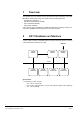
2 CS11 Hardware architecture ................................................................... 4
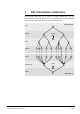
3 CS11 Information architecture................................................................5
3.1 Logical tree................................................................................................. 6
3.2 Physical tree............................................................................................... 7
3.3 Structure of the tree nodes......................................................................... 7
4 Integration of the CS11 architecture into the DMS7000......................... 8
4.1 Basis for integration ...................................................................................8
4.2 Addressing .................................................................................................8
4.3 CC11 Configuration file ..............................................................................9
4.3.1 File format ..................................................................................................9
4.3.2 Syntax ......................................................................................................10
4.3.3 Semantics ................................................................................................11
4.4 Information depth .....................................................................................13
5 CS11 Behavior in the DMS7000 ............................................................ 14
5.1 Description of the data structures ............................................................14
5.1.1 Quick-reference description .....................................................................14
5.1.2 Valid states............................................................................................... 14
5.1.3 State transition diagram ........................................................................... 14
5.1.4 Telegram repertoire.................................................................................. 15
5.2 Hierarchical level: AREA ..........................................................................16
5.2.1 Structure 1801: FIRE area .......................................................................16
5.3 Hierarchical level: SECTION (detection)..................................................22
5.3.1 Structure 1701: FIRE Section ..................................................................22
5.3.2 Structure 1702: EXTINGUISHING section...............................................23
5.4 Hierarchical level: SECTION (control)...................................................... 27
5.4.1 Structure 1751: Control Section ...............................................................27
5.5 Hierarchical level: ZONE (Detection) ....................................................... 27
5.5.1 Structure 1601: Single-detector zone....................................................... 27
5.5.2 Structure 1602: Multi-Logic zone FIRE sector (A).................................... 29
5.5.3 Structure 1602: Multi-Logic zone EXTINGUISHING sector (B) ...............31
5.5.4 Structure 1605: Manual callpoint zone..................................................... 34
5.5.5 Structure 1610: Digital zone..................................................................... 35
5.6 Hierarchical level: ZONE (controls).......................................................... 36
5.6.1 Structure 1651: Switching zone ...............................................................36
5.6.2 Structure 1654/1656: Programmable control zone ..................................37
5.7 Hierarchical level: ELEMENT (detection)................................................. 38
5.7.1 Structure 1501: Interactive detector element ...........................................38
5.7.2 Structure 1502: Interactive manual callpoint element ..............................40
5.7.3 Structure 1503: Collective manual callpoint element ............................... 41
5.7.4 Structure 1508: AnalogPlus element........................................................ 42
5.7.5 Structure 1510...1512: Collective line element......................................... 43
5.7.6 Structure 1520: Digital detection device................................................... 44
5.7.7 Structure 1521: Digital manual callpoint element..................................... 45
5.7.8 Structure 1525: Digital element................................................................ 47
5.8 Hierarchical level: ELEMENT (controls)................................................... 48
5.8.1 Structure 1551: Output element without feedback ...................................48
5.8.2 Structure 1552: Output element with feedback ........................................49
5.8.3 Structure 1560: Internal horn element...................................................... 50
5.8.4 Structure 1561: External horn element .................................................... 51