MK8000 MP4.
Table of contents About this document.........................................................................................................5 1 Safety regulations ..............................................................................................8 1.1 Country-specific standards...................................................................................8 1.2 Commissioning and testing ..................................................................................8 1.
.1 Configuration checklist .......................................................................................53 4.2 Defining MK8000 system architecture................................................................55 4.3 4.2.1 Adding FEP stations............................................................................55 4.2.2 Setting the FEP station parameters ....................................................55 MK8000 Communication drivers ..............................................
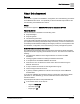
About this document About this document Purpose This manual is a guide to the installation, configuration, and commissioning procedures for the MK8000 OPC Server. It is specifically for those individuals responsible for the commissioning of the MK8000 OPC Server. Scope This document applies to MK8000 OPC Server for subsystems MP 4.60.
About this document - Advanced search criterias: Select Brochure No. and enter the document number to search for (A6V10089056). Alternatively, select Title and enter the product name (DMS8000). 2. Click Search to start. 3. In the resulting area on the right, click on Contents link to show the list of search results. For more information such as Siemens news and announcements, visit the STEP Web portal at: https://workspace.sbt.siemens.com/content/00001123/default.
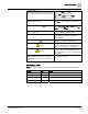
About this document designated with a ⊳. Results, after completing a step or at the end of the entire procedure, are designated with a ⇨. 1. Click the Print icon . ⇨ The Print dialog box appears. 2. Select the printer and click Print. ⇨ The print confirmation appears. Bold font in a procedure indicates something you should select or type. Type F for Field panels. Click OK to save changes and close the dialog box. Menu paths are indicated in bold.
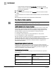
1 Safety regulations Country-specific standards 1 Safety regulations This section describes the danger levels and the relevant safety regulations applicable to the use of the products described in this manual. Please read the following work instructions as well as the preceding section About this document thoroughly before beginning any work. 1.1 Country-specific standards Siemens products are developed and produced in compliance with the relevant international and European safety standards.
Introduction What’s new 2 2 Introduction This is a guide to the software installation, configuration and commissioning of the MK8000 OPC Server. Overview MK8000 is an OPC server that can represent a number of safety and security objects as multi-state OPC items. MK8000 software can be installed on a single machine or distributed on a network. MK8000 is fully compliant with OPC Standard V2.0 (see on the Internet: www.opcfoundation.org).
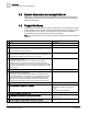
2 Introduction System dimensions and compatibility list 2.2 System dimensions and compatibility list Please refer to MK8000 Datasheet (A6V10062405). Also, the latest information and compatibility issues about the current software can be found in the product Release Notes (A6V10062455). 2.3 Project Workflows The following is an overview of the phases or steps that occur from the point-of-sale to project handover to the customer.
Introduction Project Workflows 2 able to continue without further DU support 12 System is ‘acceptance tested’. This is typically done with both the DU and the 3rd party integration team working through any problems together. 13 Project is handed over to the customer. Once the system is running according to plan, the customer accepts the system and the project is closed. 14 Maintenance contract begins.
3 Installation Installation requirements 3 Installation 3.1 Installation requirements This chapter lists hardware and software requirements for installation of the MK8000 OPC Server. The list of requirements includes network related components required for distributed (client/server) configurations. VMware virtual machines can be used as long as hardware and software requirement are matched.
Installation Installation requirements 3.1.3 3 Software requirements This section presents the software requirements for installation of the MK8000 system. Note that the English edition of the required software is available on the DMS8000 CD.
3 Installation Installation requirements 3.1.3.1 MS SQL Server notes If the MS SQL Server (2005 or 2008) is available on the machine where MK8000 is installed or on the network, it can be used for the MK8000 functions as well. The name of the SQL Server should be specified during software setup [➙ 26] or modified later using the SQL Server tab of the Engineering Tools [➙ 49].
Installation Installation requirements 3 2. In the form that appears (in the General tab), set the firewall to Off. Alternatively, the Windows firewall can be configured in order to allow the system to operate over the network. This is possible with a dedicated script provided in: \Utilities\Firewall Configuration 3.1.3.4 In this folder, double-click the file MK8000 Firewall Cnf.vbs to start the script procedure.
3 Installation Installation requirements If you do not have administration rights, you have to enter an administrator password. Be informed that this is perfectly normal and is only necessary when the program tool is started for the very first time. Alternatively, you may want to disable UAC and let the PC behaves as with Windows XP. You can do that in the Control Panel: 1. Select Start > Settings > Control Panel. 2. In the Search box on the top right of the screen, type in user account control.
Installation Installation requirements 3.1.4 3 Secure operation requirements The security of MK8000 systems requires appropriate planning and proper organizational procedures. Please review the following list of the issues to consider: 3.1.4.
3 Installation Installation requirements The system has shown good compatibility with most popular antivirus and security suite applications. In the MK8000 installation and configuration, the specific security features should be applied as required.
Installation Installation requirements 3.1.4.2 3 Data Backup and Disaster Recovery As part of the system security strategy, you need to define an effective data backup and recovery policy. This includes data and access passwords. Configuration backups MK8000 configuration backups should be performed after every project modification, and the related media stored in a safe place and possibly offsite.
3 Installation Installation types 3.2 3.2.1 Installation types Selecting the configuration The DMS8000 DVD includes various products. The installation options include: Installation type Meaning Scope Stand-alone (MM8000) and Server Station (full-featured) Install all MM8000 software layers as well as Composer and tools for configuring MM8000. Single-station with configuration tools.
Installation Installation types 3.2.1.1 3 Redundant server solution with Marathon virtual server In DMS8000 systems, the Marathon EverRun FT software can be used in order to satisfy fault-tolerant requirements. Marathon EverRun FT is a software application that can provide a Virtual server based on two identical PC machines connected over a hi-speed, dual local network. DMS8000 software can be installed on the virtual machine, which appears in all respects as a fully standard Windows system.
3 Installation Installation types For more information about Marathon solutions, refer to the following web site: http://www.marathontechnologies.com/Continuous_Avail.html Also, an online demo can be found at the following web address: http://www.marathontechnologies.com/demo.html In general, it is recommended that anyone installing, configuring, or administering a Marathon FT virtual Server environment running the DMS8000 software attend a Marathon authorized training course. 3.2.
Installation Installation checklist 3.3 3 Installation checklist The following two checklists tell you what you need for MK8000 installation, and steps you go through to install it. Items needed for installation Administrator account name and password is required. In case of a distributed system, all PCs should be in the network and configured into the same domain. It must be clear to you what type of security policy [➙ 22] you wish to apply.
3 Installation Installation procedure 3.4 Installation procedure While the installation process is relatively straightforward, there are a few items that should be noted. MK8000 and MM8000 solutions The MK8000 can be an independent OPC server or run as a component of an MM8000 management system. This document discusses the installation procedure of the first of the two options, whereas the MM8000 ICC manual (A6V10062413) should be referred to about the MM8000 product installation.
Installation Installation procedure 3.4.1 3 Welcome screen The DMS8000 CD provides a welcome page that guides you in the installation process. The page appears automatically when you insert the CD. In very special cases, if the Autorun option is disabled on your PC, you need to execute the Autorun.exe file manually in the CD main folder. As shown in the following figure, the welcome page presents a menu including the following commands: Install DMS8000 products as described here below.
3 Installation Installation procedure At that point, you will be prompted how you wish to handle this situation, and you can proceed in two ways: 1. Continuing with the installation (recommended) and skipping the installation of that software package. A higher version of the prerequisite software is already installed and is most likely compatible with MK8000. Once the installation has completed, you will be able to check the behaviour of the MK8000 software to ensure that it functions properly. 2.
Installation Installation procedure 3 Folder selection step 3. In the installation type selection page, choose the type of station among the following: For more information, see Installation types [➙ 20].
3 Installation Installation procedure 4. Click Next to continue. SQL connection parameters SQL available on local PC In the SQL Server page (Stand-Alone or Server type only), if an SQL server is available on the local PC or if you intend to install it locally: Leave the default selection Local Default and click Next to continue. SQL Server step (standard option) SQL server is available If an SQL server is available on the network or if you wish to customise the SQL name and/or access security: 1.
Installation Installation procedure 3 PCs involved in the OPC communication, both server and client(s). Do not remove this user. - Advanced: the internal username and password can be specified as desired. You can specify a new user account or an existing one. (See Selecting the type of Windows security [➙ 22]). Selecting the MK8000 security option 2. Click Next to continue. Automatic Server start-up and Redundancy option 1.
3 Installation Installation procedure Selecting the Automatic Server Startup and Redundancy 2. Click Next to continue. Server PC name (Client/FEP station only) 1. If installing a Client or FEP station, enter the network name of the server (StandAlone) station. Note that the IP address is not valid. 2. Click Next to continue. Software setup 1. Click Install. Starting the software installation At this point, the setup copies the file onto the hard disk and performs the initialisation tasks.
Installation Installation procedure 3 Copying files 2. If a reboot is required, when the PC starts up again: - Logon in Windows using the same username. 3. If the installation of a local SQL Server is required: - Refer to Installing a local SQL Server [➙ 32]. Setup complete The setup procedure is now complete, the following window appears. DMS8000 setup complete Here you can also immediately start the System Monitor (see A4 - Using the System Supervisor Browser [➙ 92]).
3 Installation Installation procedure 3.4.3 3.4.3.1 Installing a local SQL Server Installing SQL Server 2005 Express + Backward Compatibility Pckg If you do not already have an SQL Server installed, the installation procedure automatically starts the SQL Server 2005 Express SP3 setup and the SQL 2005 Backward Compatibility package setup (English edition). Microsoft .NET V2.0 framework library is a pre-requisite automatically installed for SQL Server 2005 Express. Installing SQL Server 2005 Express 1.
Installation Installation procedure 3 Microsoft SQL Server Installation Wizard 5. The installation procedure performs a configuration check to ensure that hardware and software requirements are matched. In the resulting window, you can find any errors or warnings found (see the Status column). Use the Filter command to limit what items are visible in the list. Follow the Message link and read any related information that may indicate if and why your system cannot fully support SQL software.
3 Installation Installation procedure Filling in the SQL Server 2005 Express registration information 8. Next, the Feature Selection window shows the list of components. Do not modify the default setting and just click Next. Selecting the SQL Server 2005 Express features to install 9. The next window allows setting SQL authentication mode. Confirm the default option (Windows Authentication Mode) and click Next. 34 Building Technologies Fire Safety & Security Products A6V10062407_a_en 30.06.
Installation Installation procedure 3 Selecting the SQL Server 2005 Express authentication mode 10. The following configuration window allows configuring the SQL user options. In general, we recommend enabling both options (Enable User Instances and Add user to the Server Administration role) unless specific security issues apply (contact IT Manager). Configuring the SQL Server 2005 Express users 11.
3 Installation Installation procedure Setting SQL Server 2005 Express Error and Usage Reports Ready to install SQL Server 2005 Express 12. At this point, setup installs the software. This may take a few minutes. A setup progress window displays on the screen, and a summary log is finally available in the next window. Click Summary Log to open and possibly save the log file.
Installation Installation procedure 3 SQL Server 2005 Express setup finished SQL Server 2005 Express setup summary log 13. Click Finish to close the setup procedure. You now need to add the Backward Compatibility Package. 37 Building Technologies Fire Safety & Security Products A6V10062407_a_en 30.06.
3 Installation Installation procedure Installing Backward Compatibility Package 1. In the Welcome window, click Next and Next again to confirm you accept the License Agreement. Installing SQL Server 2005 Express Backward Compatibility Package License Agreement for Backward Compatibility Package 2. At this point, fill in the registration information. 38 Building Technologies Fire Safety & Security Products A6V10062407_a_en 30.06.
Installation Installation procedure 3 Filling in the Backward Compatibility Package registration information 3. Next, the Feature Selection window shows the list of components. You may use the Disk Cost function to check the disk space available and the detailed requirements. Do not modify the default setting. Just click Next and then, in the subsequent window, click Install.
3 Installation Installation procedure Ready to install the Backward Compatibility Package 4. At this point, the setup installs the software. When completed, click Finish to close the last setup window. Completing the Backward Compatibility Package setup 40 Building Technologies Fire Safety & Security Products A6V10062407_a_en 30.06.
Installation Installation procedure 3.4.3.2 3 Installing the SQLXML 3.0 software An extension to the standard MS-SQL software is also required for handling XML files. This is a free package from Microsoft named SQL XML 3.0. If necessary, the installation procedure automatically starts SQLXML V3.0 setup wizard. Starting the SQL XML Installation Wizard You must accept the terms in the license agreement, then enter your name and company, and finally confirm the installation folder.
3 Installation Installation procedure 3.4.4 Activating the software license At this point, you need to connect and activate the license key and restart the PC. The software required for handling the license key is automatically installed with the MK8000 setup. In order to manage the MK8000 software license, please note the following information. Composer license MK8000 and the Composer tool software require a license to fully enable their features. Composer requires a license to enable all its features.
Installation Installation procedure 3 Demo mode MM8000/NK8000 and MK8000 can operate in demo mode for a limited amount of time. The following table illustrates the system behaviour. Composer and system behaviour in relation to the license options. Missing key or invalid/insuf ficient PAK Missing key and no PAK code installed Customer Key and PAK (including Composer) Composer Can Open/Close /Download/ Backup. Can also support limited configuratio n capabilities (e.g. for NK8237).
3 Installation Installation procedure The resulting list shows the required license parameters for the current configuration. 3. Click Check License Data to verify whether the license and PAK codes currently loaded can enable the configuration. The Available License column will then show Available if the license PAK is sufficient. Viewing and checking the MK8000 license 3.4.6 Starting the system for the first time When a valid PAK code is inserted, the PC can be restarted.
Installation Installation procedure 3.4.7 3 Installing the software on the FEP (Distributed Systems) When you install MK8000 on a FEP, you need to know the name of the PC where you want to install the server (Stand-Alone). To install MK8000 on a FEP station, do the following: 1. Logon as Administrator. 2. Insert the DMS8000 Installation CD. 3. Follow the procedure described in section Software set-up [➙ 26]. 4. In the setup menu, select FEP Station. 5.
3 Installation Installation procedure 3.4.10 Testing Server and FEP communication After you have connected and activated the PAK, and rebooted the PC, you should verify that the Server and FEP stations (if any) are communicating correctly. You do this with the System Supervisor Browser (For more information on the System Supervisor Browser, see A4 - Using the System Supervisor Browser [➙ 92]): Select Start > Programs > MK8000 > System Supervisor Browser.
Installation Installation procedure 3.4.12 3 Menu applications MK8000 setup installs the following applications, available in the Start > Program > DMS8000 menu Main applications Icon Name Description Tools See the following table. Composer Configuration tool for configuring the OPC Server. DMS8000 System Monitor Resident monitor or DMS8000 applications. It shows the icon on the right side of the Windows taskbar. Refer to Appendix A - System supervision and event simulation [➙ 86].
3 Installation Installation procedure 3.4.13 Technical utilities The following utilities are also installed along with MK8000 software, although they are not directly available on the programs menu. 3.4.13.1 Program Utilities The folder \Utilities\ contains various sub-folders with utility programs. Some of them can be used by you for specific purposes and are documented here. WARNING We recommend using these applications carefully.
Installation Installation procedure 3.4.13.2 3 Program Tools In \Utilities\, the Tools subfolder contains additional useful software components. The list includes: Engineering Tools This utility allows changing various internal options and initialising databases. Launch the tool running the Engineering Tools.exe file in \Utilities\Tools. The tool presents a multi-tab window providing various functions.
3 Installation Installation procedure 3.4.13.3 Batch commands The folder: \Utilities\Bat contains the following batch procedures: NK8210ConfigurationTool.exe This program initialises the IIS (Internet Information Service) for the NK8000 Web Server to work. It should be used when the IIS software is installed after MK8000 and requires a specific initialisation.
Installation Installation procedure 3 NK8000 communication log file (technical support use only) NK8210 - LogFileYes.reg NK8210 - LogFileNo.reg Enable/disable the disk file logging of NS8210 driver. Do not enable this mode unless explicitly instructed by FS DMS support. The log files are created in the folder: \Communication Layer\Driver NS8210 and they are named according to a scheme that includes the creation date and time stamp: NK8210Log_ddmmyy_hhmmss.txt, e.g.
3 Installation System internal user account 3.4.14 3.4.14.1 Further files NK8000 firmware NK822x (NK8222, NK8223, NK8225) The latest release of the NK822x firmware is provided in the folder: \NK822x - Firmware The firmware is contained in compressed (ZIP) files. The list includes: NK8223_x.yy_Build_zz.zip (for NK8222 and NK8223 units) NK8225_x.yy_Build_zz.
Configuring MK8000 Configuration checklist 4 4 Configuring MK8000 DMS8000 configuration process overview The configuration checklist is a general guide to the larger configuration process. The order in which you perform the tasks in the checklist may vary depending on your personal preference. This is not an absolute guide, but rather lends context to the tasks discussed in this manual. Note: A similar configuration list is provided in the Network, Fire, and Intrusion Connectivity configuration guides.
4 Configuring MK8000 Configuration checklist – Intrusion subsystems (DMS8000 Intrusion Connectivity configuration guide) – Video network (DMS8000 Video Connectivity configuration guide) – Access Control system (DMS8000 Access Control Connectivity configuration guide) Configure the communication network. (DMS8000 Network Connectivity configuration guide) Link the subsystems to the communication network. (DMS8000 Fire Connectivity configuration guide).
Configuring MK8000 Defining MK8000 system architecture 4.2 4 Defining MK8000 system architecture Overview When setting up your project in Composer, the first thing you should do is to represent your MK8000 architecture. Note that, unlike previous MK8000 software releases, any new project includes the basic internal system structure, which will already be set up for you. Internal MK8000 structure in a new project 4.2.1 Adding FEP stations To add the FEP stations to the project; do the following: 1.
4 Configuring MK8000 Defining MK8000 system architecture Name (localhost) and IP address (127.0.0.1) fields are already set for this configuration. Do not change this setting. WARNING After MK8000 has been installed, any change in the computer name of the stations requires a special procedure. Refer to the Engineering Tools described in section Program Tools [➙ 49].
Configuring MK8000 MK8000 Communication drivers 4.3 4 MK8000 Communication drivers On the MK8000 Stand-alone and FEP stations, you need to add the drivers that provide the communication services for the OPC server. Several types of drivers are available, and you should select them according to the actual connections to be made with network devices and control units. MK8000 network drivers The drivers are organised in groups (channel or manager); the list includes: 4.3.
4 Configuring MK8000 Setting vitality 3. Select the serial Channel node (by default Channel). 4. Add the required drivers by clicking the corresponding icon on the left. - NS8010 Cerloop/ISO1745 - NS8012 CDI-Net - NS8210 NK8000 - NS8015 CNDL - NS8014 SI410 - NS8011 BACnet - NS8013 SPC On the MK8000 FEP station you can also add serial drivers as previously described and then connect them (drag & drop) to the Channel node of the Stand-alone station.
Configuring MK8000 Setting OPC Group names and access limitations 4.4.1 4 Connecting a CS11 (and FC700A) directly to the MK8000 When connected directly to the MK8000, CS11 AlgoRex and FC700A require supervision by the vitality check. Connecting a CS11/FC700A to the MK8000 To connect a CS11/FC700A to MK8000, do the following: 1. In the subsystem Node tab of CK11 (FG700A) and CC11 (FC700A), set the vitality timer (in seconds). 2. Drag the CK11(FG700A) to the MK8000 Cerloop Driver.
4 Configuring MK8000 Setting the Multi-state value data format Setting the group name and full access rights for an FS20 unit 4.6 Setting the Multi-state value data format The OPC data item provided by MK8000 (multi-state item) can assume two alternative structures: Threshold mode: The item value will be a number represented in 2 bytes; the possible states will correspond to specific values.
Configuring MK8000 Setting up the diagnostic log 4.7 4 Setting up the diagnostic log The MK8000 will record all system activity in a log file, which you can access for troubleshooting and debugging purposes. If you want to modify any of the default settings for this log, you can do it now, or wait until you have an immediate need for it. Setting the diagnostic log options Item Choose… 1 Where the file will be located. 2 What the file will be called. Default name is MK8000.log.
4 Configuring MK8000 Downloading 4.8 4.8.1 Downloading Backing up your data When the configuration process is complete, do not forget to backup your project from the Composer Projects Management window. Detailed instructions for this are located in the Composer Technical Manual (A6V10062401). After you have backed up the project you are ready to transfer the configuration to the MK8000 Server. 4.8.
Configuring MK8000 Downloading 4.8.4 4 Downloading the configuration There are two types of downloads that can be performed: Regular Download (downloads the complete project) Incremental Download (downloads only the changes) A regular download transfers all of the data contained in the Composer project to the MK8000 server. An incremental download transfers only the information that has changed since the last download.
4 Configuring MK8000 Downloading Download checks As a very first step, the download procedure verifies the consistency of the entire data set to download. In case of problems, for example if an operating procedure or a reaction program are not properly configured, a message informs you about the inconsistency (see the following examples). At that point, you can: Abort the current download, to let you correct the problem and then start a new download.
Testing the configuration 5 5 Testing the configuration Once you have downloaded the configuration to the MK8000, you need to perform the following tests with an OPC client. For a list of OPC Clients and other valuable OPCrelated information, go to www.opcfoundation.org on the Internet. There are three main elements to check.
5 Testing the configuration 3. Do the following: - If you are connecting to the server from a remote client, then select the Remote Connection check box and select the station where the server resides. - If your OPC Client supports a limited number of characters for objects, then check the Use short item name check box (names will be limited to 50 characters). - The next option concerns the number of items per object, which can be one or three.
Testing the configuration 5 2. Verify that all the subsystems are displayed in this list. Note: The subsystem names that are displayed here correspond with the OPC group names [➙ 59] entered in the MK8000 tab of Composer during the configuration process. 3. Use the Add Branch button to insert subsystems into the main window for testing, and select Done when finished. The subsystems appear in the main window of the client.
5 Testing the configuration Checking the values of the objects and their children When checking values, note that the grid to the right of each selected node shows both the attributes of the selected node and the attributes of its child nodes. In addition, a real time transaction log is shown. To open the properties page, do one of the following: - Use the Properties page icon - Double-click on the node selected. To display more information on the grid, select View > View Advanced.
Testing the configuration 5 Connecting the network subsystem, and verifying correct communication To connect the network subsystem to the field, and confirm that MK8000 communicates correctly with the subsystems, do the following: 1. One by one, physically connect the network subsystem or gateway with the MK8000 OPC server. 2. Verify that each OPC Object turns green, and shows the corresponding value of the subsystem and Quality: GOOD. Note: It takes a minute for child nodes to change to GOOD. 3.
6 Tips for Integrating with an OPC client Exporting data to a 3rd party OPC Client 6 Tips for Integrating with an OPC client This section contains general tips to help facilitate the process of integration with an OPC client. 6.1 Exporting data to a 3rd party OPC Client Once you have completed the OPC Server configuration, the data is ready to be exported for use by the 3rd party integration team. An application called Export Wizard was installed along with the MK8000 for generating export files.
Tips for Integrating with an OPC client Exporting data to a 3rd party OPC Client 6 Select the fields to be included in the table 3. Click Next to go to the Additional settings window. Additional Settings window 4. Use the following checklist to specify your settings: - Perform a coherence test. The coherence test checks for duplicate OPC object names in the configuration. Typically this feature isn’t used. - Select the character to separate each field.
6 Tips for Integrating with an OPC client Using the test client Once the .CSV file has been generated, you can open it in MS Excel and then convert it to a MS Access© file, if desired. 6.2 Using the test client You may want to use the MK8000 test client on the client stations for commissioning and debugging purposes. You can choose to install the test client only during product installation. Run the MK8000 installation application as usual on the client and select Client from the installation type list.
Tips for Integrating with an OPC client Possible difficulties in integrating an OPC client 6 You need to create the EXACT SAME user account names AND passwords on BOTH machines. This does not mean that you must be logged in as the same user on both machines to get the system to work, just that the same user/password combination must be defined on each machine. See the following general guidelines: For a distributed configuration, the OPC Server and Clients must be part of the same workgroup or domain.
6 Tips for Integrating with an OPC client Possible difficulties in integrating an OPC client 6.4.2.1 Changing the auto start setting 1. Open the services menu (Start > Programs > Administrative Tools > Services or Start > Settings > Control Panel > Administrative Tools > Services) 2. Select DixieSystem Supervisor. 3. Right-click DixieSystem Supervisor to display the Properties pop-up window. 4. Select the Automatic in the Startup type drop-down menu in the General tab.
Tips for Integrating with an OPC client Possible difficulties in integrating an OPC client 6 Access These permissions allow a client machine to connect to a server, retrieve a list of OPC servers, and connect to an OPC server application. They also allow the OPC server to make what is known as a callback to your client. A callback occurs when you ask the OPC server to notify your client only when data changes. Launch These permissions are what allow an OPC client application to start or launch an .
6 Tips for Integrating with an OPC client Possible difficulties in integrating an OPC client Selecting the computer DCOM configuration Note 1: You must be authorized to use dcomcnfg.exe (administrator) – ask your system administrator to set your DCOM if you are not. Note 2: Some changes in DCOM settings require rebooting the computer for changes to take an effect (for example, DCOM enable/disable). 6.4.2.
Tips for Integrating with an OPC client Possible difficulties in integrating an OPC client 6 Default Properties tab Check Enable Distributed COM on this computer. In addition, make sure that the Default Authorization Level shows Connect and the Default Impersonation Level are set to Identify. Uncheck the Additional security for reference tracking check box (match the settings in the following figure). Default Properties tab Default Protocols tab We recommend that you use Connection-oriented TCP-IP.
6 Tips for Integrating with an OPC client Possible difficulties in integrating an OPC client MSDTC tab This tab contains some parameters related to log information and tracing options. We recommend to keep the local coordinator option checked and not to modify the other default settings. Default Security tab Note: When setting permissions for users, please note that Administrator is the administrator of the local machine. To set permissions for users, do the following: 1.
Tips for Integrating with an OPC client Possible difficulties in integrating an OPC client 6 3. Select Edit Default in the Launch and Activation Permissions section of the COM security tab. 4. Allow local and remote Launch and Activation to the authorised users. Note: In general, you should include at a minimum the group INTERACTIVE so that local logged in users can launch the server and, if you are running the OPC server as a service, you may need the SYSTEM account included as well.
6 Tips for Integrating with an OPC client Possible difficulties in integrating an OPC client 6.4.2.5 Specific MK8000 DCOM settings To select the MK8000 DCOM properties, perform the following steps: 1. In the Component Service window, right-click the node: Component Services > Computers > My Computer > DCOM Config > MM8000Server. 2. In the menu that appears, select Properties.
Tips for Integrating with an OPC client Possible difficulties in integrating an OPC client 6 MM8000Server Properties - General tab Location tab - MM8000Server Properties Make sure that the Run application on this computer is the only check box checked.
6 Tips for Integrating with an OPC client Possible difficulties in integrating an OPC client MM8000Server Properties - Security tab Endpoints tab - MM8000Server Properties We recommend leaving the Endpoints level to Default. This means that this server will use the protocols that were set up on the Default Properties tab in the DCOM Config utility.
Tips for Integrating with an OPC client Possible difficulties in integrating an OPC client 6 This user: you may specify the user whose security context will be used to run the application. The system account: this is available only for services that use DCOM.
6 Tips for Integrating with an OPC client Integrating clients that do not support DCOM 6.5 Integrating clients that do not support DCOM The MK8000 server uses DCOM (Distributed Component Object Model) to communicate via network for distributed configurations. In the event that your OPC client does not have DCOM capability, you can install this script on the client PC to create the illusion that the OPC server resides on the OPC client, and permits them to communicate effectively.
Tips for Integrating with an OPC client Integrating clients that do not support DCOM 6 Removing OPC Transparency Support Once installed, the OPC Transparency values should not be deleted from the registry manually. Instead, use the utility provided to remove it. Please note that OPC Transparency should not be deleted from the PC where the OPC server resides. To remove the OPC Transparency registry values, do the following: 1. Copy the Delete Transparent OPC.
Appendix A - System supervision and event simulation A1 - System Monitor Appendix A - System supervision and event simulation A1 - System Monitor The System Monitor is an application that is installed with MK8000. As its name implies, it monitors the MK8000 system and reports the status of the server and FEPs. In general, the System Monitor helps you quickly perform the following tasks: Check the MK8000 status at a glance (for example, whether or not the MK8000 server is running).
Appendix A - System supervision and event simulation A1 - System Monitor Right-click menu When you right-click the System Monitor icon, a menu displays and includes the following: Start or Stop Server: depending whether the system is running or not, only one of the two commands is active. Advanced: open a further submenu (see below). System Supervisor Browser: launch the browser (see below).
Appendix A - System supervision and event simulation A1 - System Monitor Advanced menu The Advanced menu includes the following: Start Server in Simulation Mode: start the system with an additional application that allows simulating field events [➙ 89]. While running in this mode, MK8000 does not communicate with the field, but only with the simulator. Simulation Settings: this command permits to set the name of the simulation PC.
Appendix A - System supervision and event simulation A2 - Simulating field events A2 - Simulating field events Starting the MM8000 Server in Simulation mode In the Advanced menu, you can start the MK8000 server in simulation mode. This mode results in starting an additional application (Field Simulator), which allows generating messages as though they were coming from the fire and intrusion control units in the field.
Appendix A - System supervision and event simulation A2 - Simulating field events Limits Note the following limitations of the Field Simulator: The events from the SiPass Access Control system and from the CCTV Network cannot be simulated with the standard Field Simulator. In a few cases, state and commands may not be properly working after an incremental download, e.g. when simulating the conditions in multiple selections of points.
Appendix A - System supervision and event simulation A3 - Simulating from a networked computer A3 - Simulating from a networked computer The Field Simulator program can also run on a separate computer and connect to the MK8000 server over a LAN connection. However, this solution requires a special setting.
Appendix A - System supervision and event simulation A4 - Using the System Supervisor Browser A4 - Using the System Supervisor Browser The System Supervisor Browser can be launched from the MK8000 System Monitor menu in the Windows tray or via the Windows Programs menu (Start > Programs > DMS8000 > System Supervisor Browser). The browser shows the running MK8000 stations (“A” in the following figure) and the associated tasks (“B” in the following figure).
Appendix B - Enabling Server auto-start Appendix B - Enabling Server auto-start During normal use of MK8000, it is convenient to have the MK8000 Server start automatically upon system start-up. During troubleshooting and system testing, however, it may be more convenient to disable auto start. To change the auto start settings, do the following: 1. Open the services menu: Start > Settings > Control Panel > Administrative Tools > Services 2. Select DixieSystemSupervisor. 3.
Appendix C - How to use CSV Files Appendix C - How to use CSV Files The CSV (Comma Separated Values) files are best viewed within applications that allow manipulating data that is in columnar format. Common examples of such applications are those that are used to create spreadsheets and databases. If you do not have access to either a spreadsheet or a database application, you can also retrieve the data table file into a word-processing application.
Appendix D - How to modify MK8000 projects for MM8000 Appendix D - How to modify MK8000 projects for MM8000 In Composer, MM8000 and MK8000 projects are quite different (MM8000 requires many more system nodes and extensions than MK8000). Given an existing MK8000 project, it is possible to make it compatible with MM8000 by following the procedure illustrated here below. Instead, it is not possible to modify an MM8000 Composer project for adapting it to the MK8000 OPC Server.
Appendix D - How to modify MK8000 projects for MM8000 Note: Each subsystem (a control unit or a network component) may or may not be handled by the OPC server depending on the Exposed in the OPC interface option available in the MK8000 Extensor tab. 96 Building Technologies Fire Safety & Security Products A6V10062407_a_en 30.06.
Issued by Siemens Switzerland Ltd Infrastructure & Cities Sector Building Technologies Division International Headquarters Gubelstrasse 22 CH-6301 Zug Tel. +41 41-724 24 24 www.siemens.com/buildingtechnologies Document ID A6V10062407_a_en Edition 30.06.2013 © 2013 Copyright Siemens Switzerland Ltd Technical specifications and availability subject to change without notice.