MM8000 MP3.
Data and design subject to change without notice. / Supply subject to availability. © 2008 Copyright by Siemens Switzerland Ltd We reserve all rights in this document and in the subject thereof.
About this document...............................................................................................1 1 1.1 Introduction .............................................................................................3 Version supported .....................................................................................3 2 2.1 2.1.1 2.2 2.2.1 2.2.2 2.2.3 2.2.3.1 2.2.4 2.3 2.3.1 Installation ...............................................................................................
Introduction About this document Purpose of this document This manual is a guide to the installation, configuration, and operations for the MM8000 Management Stations MP3.20 that includes the MAXSYS intrusion control units. It presents the ‘add-on’ module for the MAXSYS support.
Introduction Operational and safety regulations Before beginning work on the MM8000 Management Station for the MAXSYS, you must have read and understood. the Operational and Safety Regulations included in the following documents: – 007083 - DMS8000 Network, Fire and Intrusion Connectivity Configuration Guide. – 006799 - MM8000 Installation, Configuration and Commissioning. – 007798 - NK8000 Installation, Configuration and Commissioning.
Introduction 1 Introduction The MAXSYS is an intrusion security system based on the PC6010 control unit, which can support up to 256 zones (16 on the main board and the rest on PC6108A 8-zone expansion modules) in 32 separate areas. The user interface is based on the PC6501 panels (max 64), which can guide users through the available options according to their access level (basic, advanced, supervisor, or master).
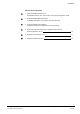
Installation 2 Installation 2.1 Distribution package The MM8000 MP3.20 software for the MAXSYS support is distributed as an addon package, to be installed on the stations including the Composer tool (client-only and FEP stations are therefore excluded) after the standard MM8000 MP3.20 Setup. The package is named: ‘MM8000 - Subsystem extension N. 02 (Maxsys V1.0)’. Installation kit The installation kit includes (Fig. 1): • The new help files, describing the MAXSYS configuration procedures.
Installation INSTALLATION CHECKLIST 1. Install the MM8000 hardware key DMS8000 Network, Fire, and Intrusion Connectivity Configuration Guide 2. Install the MM8000 MP3.20 Software MM8000 Installation, Configuration and Commissioning 3. Install the NK8000 units (NK822x) NK8000 Installation, Configuration and Commissioning 4. On the station(s) with configuration capability (Composer tool), install the MAXSYS add-on p. 6 5. Install the new Subsystem Tool p. 7 6. Update the NK8000 firmware p.
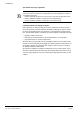
Installation 2.2 Software installation 2.2.1 Requirements The support for MAXSYS does not add any special requirements to the standard MM8000 MP3.20. Therefore, software and hardware requirements are the same as for the base MM8000 MP3.20 software, as described in the document no. 006799, MM8000 Installation, Configuration and Commissioning. As far the NK8000 network is concerned, the requirements are described in he document no. 007798, NK8000 Installation, Configuration and Commissioning. MM8000 MP3.
Installation Fig. 2 Starting the add-on installation 2. Installing the Subsystem Tool Composer requires that the tools are installed using a specific procedure. Therefore, a small utility is also launched in order to add the MAXSYS Subsystem Tool (ST) in to the Composer tool set. The utility shows as illustrated in Fig. 3. Click ‘Install’ to proceed. The installation procedure requires the account name and password of the MM8000 “internal user”.
Installation Fig. 4 Closing the tool installation 2.2.3.1 Multiple add-on’s installation In general, it is possible to install multiple add-on packages and benefit of their combined functionalities. However, we recommend care in the firmware update (see next chapter). 2.2.4 MAXSYS add-on uninstall The MAXSYS add-on module cannot be uninstalled. 8 Building Technologies Fire safety & Security Products 008751_b_en MaxSys - MM8000 3.20 add-on.doc 05.
Installation 2.3 Communication network The MAXSYS is connected to the MM8000 system by means of the NK8000 network and namely via the NK8222, NK8223, or NK8225 units. In order to communicate with the MAXSYS, the NK822x units should however be equipped with a new firmware that is included in the installation package as an additional component (DLL) to be added to the standard firmware file set.
Installation 2. Start Composer and open the project that includes the MAXSYS units. 3. Expand the ‘Channel collection’ folder in: Supervision System Settings MM8000 System Station (or FEP) Channel collection. Physical configuration 4. Select the ‘NS8210 driver’ node and then the ‘Download’ tab (Fig. 6). Fig. 6 ‘Download’ tab 5. Select all the branches (NK822x) in the list located in the upper part of the form.
Installation Fig. 8 Opening the new NK822x firmware files Fig. 9 New NK822x firmware (MAXSYS add-on) in the Firmware List Note that the “_02” suffix in the firmware name indicates the add-on index (02 for the MAXSYS). 7. Select the new firmware version in the Firmware List. 8. Click the button “Download Firmware”. The download procedure starts. The new firmware is downloaded to the NK822x units via FTP (File Transfer Protocol) services over the network. 9.
Configuration 3 Configuration 3.1 Configuration checklist Verify that you have satisfied the items needed in the first checklist before proceeding to the configuration checklist that follows. ITEMS NEEDED FOR CONFIGURATION The intrusion system architecture: number of control units (PC6010) and interfaces (PC6442) The encryption key for the communication security (=0 if no encryption is required). The local address (1 to 32) for each control unit.
Configuration 3.2 Configuration procedure The following are the configuration procedures for the MAXSYS control unit: Adding the folder for the MAXSYS system 1. Open the Composer project. 2. Create a folder for the control unit. Adding the main MAXSYS node (PC6442 interface) 1. Select the new folder. 2. Select the MAXSYS icon (see Fig. 10): The new node is added to the project structure. By default, the node will be named ‘PC6442 Maxsys Interface #1’.
Configuration 2. Set the ‘Private key’ field. This is an 8-character field that should match the hexadecimal value set in the PC6442 unit (Fig. 11). Fig. 11 Setting the MAXSYS encryption key Adding the MAXSYS control unit nodes (Panel Application) 1. Select the PC6442 Maxsys Interface node. 2. Select the MAXSYS CPU icon (see Fig. 12): The new node is added to the project structure. By default, the node will be named ‘Panel Application #1’.
Configuration – Select the file and click ‘Open’ (Fig. 14). In a few moments, the unit structure is imported. Fig. 13 Starting the import procedure The CSV file is unique for the entire MAXSYS system, i.e. it includes all the panels (CPU nodes) for a given interface node. Nevertheless, the import procedure must be executed at panel level and the same CSV file selected for the set of associated panels. Fig. 14 Selecting the metafile CSV files can be re-imported after a configuration change.
Configuration Manual configuration If you are not able to import the configuration, you can configure the MAXSYS system by hand to reflect the actual control unit configurations.
Configuration Fig. 15 Link MAXSYS to the NK8000 network When the link is established, a new node appears on the structure tree, and its properties can be seen on the ‘Link’ tab of both the connected nodes. Downloading the MM8000 configuration Before operating with the new MM8000 configuration, you need to download it. In Composer, the download command is available in the Tools menu. The preparation to the download is discussed in the document no.
Operations 4 Operations MM8000 operations are described in the document no. 6798, MM8000 Operation Manual. Specifically, the possible events related to MAXSYS control units are listed in the table below. Notes: • When an alarm occurs, both Area and Zone objects generate an event message. Also, the MAXSYS control unit requires that the Area gets acknowledged before resetting the alarm on the Zone.
Operations Node PC6442 interface node Backbone Alarms Tamper Fault: Power supply PC6443 Interface Panel (Control Unit) Faults Fault: Fault: Tamper Fault: Fault: Other events - internal fault - RS232 fault - internal fault - connection fault - AC fault - battery fault - internal fault - RS232 fault - connection fault Primary line Fault: - line fault Infranet Fault: : - line fault PC6010 Main board Zone Fault: - internal fault Fault: - internal fault Fault: - internal fault Backbone Fau
Siemens Switzerland Ltd Building Technologies Group International Headquarters Fire Safety & Security Products Gubelstrasse 22 CH-6301 Zug Tel +41 41 724 24 24 Fax +41 41 724 35 22 www.sbt.siemens.com Document no. 008751_b_en Edition 09.