
User Manual


2
Modbus Interface Specifications
Modbus Data Model
24
Building Technologies
A6V10316242_a_en
CPS Fire Safety
31.05.2019
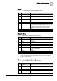
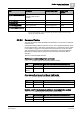
Bit
Information
Notes
2
Pre-alarm, Not ready
and other abnormal
states
Pre-alarm, Not ready, and other abnormal condition
1)
3
Alarm
Alarmed
1)
1)
If the Channel Delegation option is configured, the Pre-alarm and Alarm events are on the
element level (not the Zone level).
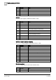
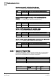
Detection element (compact)
CT_LogChan (Input registers, default base address: 9000)
Bit
Information
Notes
0 (lsb)
Fault
Faulty
1
Active
Alarmed
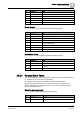
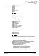
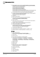
2.2.2.5 Bit Status Tables
The bit status tables (input registers) presents individual on/off event conditions for
specific objects (detection zones, detection elements, controls, and control
elements) and related conditions, for example,
detection zone alarms
. In each
table, the value 1 indicates that the condition is present on the corresponding
object. The list of objects is defined at configuration time.
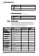
The table below collects the list of bit status tables.
Table
Information
Related object type
Default base
address
BT_ZoneAlarm
Detection zone alarmed
1)
Detection zones
21000
BT_ZonePreAlarm
Detection zone pre-alarmed
1)
Detection zones
22000
BT_ZoneNDV&Notready
Detection zone not ready or in
other abnormal state
Detection zones
23000
BT_ZoneModeOff&Test
Detection zone in test mode or
excluded
Detection zones
24000
BT_LogChanActive
Detection element (logical
channel) active
Detection elements
10000
BT_LogChanFault
Detection element (logical
channel) faulty
Detection elements
11000
BT_
LogChanModeOff&Test
Detection element (logical
channel) in test mode or
excluded
Detection elements
12000
BT_CtrlAlarm&Active
Control alarmed or activated
Controls
13000
BT_CtrlNDV&Fault
Control faulty or in other
abnormal state
Controls
14000
BT_CtrlModeOff&Test
Control in test mode or excluded
Controls
15000
BT_CtrlChanActive
Control element (control
channel) active
Control elements
16000
BT_CtrlChan Fault
Control element (control
channel) faulty
Control elements
17000