
User Manual


2
Modbus Interface Specifications
Modbus Data Model
26
Building Technologies
A6V10316242_a_en
CPS Fire Safety
31.05.2019
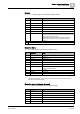
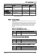
Detection zone on/off: include/exclude the zone
CMDT_Zone (Holding register, default base address 26000)
State
Command (dec)
New state after a successful command execution
Off
5
On
On
6
Off
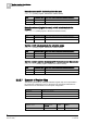
Detection element (logical channel) on/off: include/exclude the
detector
CMDT_LogChan (Holding register, default base address 27000)
State
Command (dec)
New state after a successful command execution
Off
5
On
On
6
Off
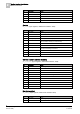
Control on/off: include/exclude the actuation group
CMDT_Ctrl (Holding register, default base address 28000)
State
Command (dec)
New state after a successful command execution
Off
5
On
On
6
Off
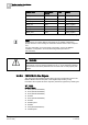
Control element (control channel) on/off: include/exclude the actuator
CMDT_CtrlChan (Holding register, default base address 29000)
State
Command (dec)
New state after a successful command execution
Off
5
On
On
6
Off
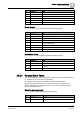
2.2.2.7 Example of Register Map
The following illustrates an example of NK8237 register map as it is presented in
the Composer configuration tool. For the panel map, the default addresses are
listed and can be customized in the Composer configuration.
Field Device
Modbus slave address
NK8237
4
FC20 Panel 1
5
FC20 Panel 2
6
Field Devices: example including two FC20 fire panels
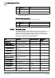
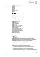
Modbus Table
Modbus Base
Address
Offset
Register
DateTime
1060
0
Holding register