
User Manual


2
Modbus Interface Specifications
Modbus Data Model
28
Building Technologies
A6V10316242_a_en
CPS Fire Safety
31.05.2019
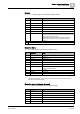
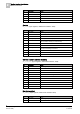
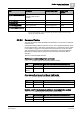
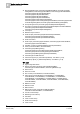
Modbus Table
Modbus Base
Address
Offset
Register
CMDT_FC20
25000
0
Holding register
CMDT_Zone
26000
0
Holding register
CMDT_LogChan
27000
0
Holding register
CMDT_Ctrl
28000
0
Holding register
CMDT_CtrlChan
29000
0
Holding register
CMDT_Section
30000
0
Holding register
CMDT_Area
31000
0
Holding register
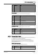
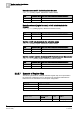
Panel map: default base address of the available tables, organized by object type
Note: The default base addresses listed above may not exactly match the
addressed of your system. Before using them for any related configuration,
please check the current settings of the Modbus master station in the Composer
tool.
For more information on the Composer configuration, refer to the NK8237
Installation, Configuration, and Commissioning Guide (document no.
A6V10316241).
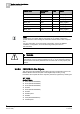
WARNING
The convention of Modbus base addresses frequently found, namely 3xxxx for
input registers, 4xxxx for holding registers and so on, is not followed by NK8237.
Note that some tools strictly based on this convention will not work properly with
NK8237.
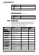
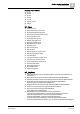
2.2.2.8 FS20/FS720 Fire Objects
This section lists the FS20/FS720 fire objects and the corresponding types in the
NK8237 Modbus data model (refer to the Register Map section [➙ 16]).
Here below the complete list of fire objects is presented, organized by model types.
WT_FC20
Sinteso™ FS20:
FC20 (PanelFc2020Elem)
FC30 (PanelFc2030Elem)
FC40 (PanelFc2040Elem)
FC2050
FC60 (PanelFc2060Elem)
FC2080
FG2004 panel
FG2020
FT20 (PanelFt2040Elem)
FT2080 panel