
User Manual


2
Modbus Interface Specifications
Modbus Data Model
34
Building Technologies
A6V10316242_a_en
CPS Fire Safety
31.05.2019
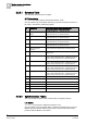
2.2.3 STT20 Register Map
Data Representation
The NK823x Modbus gateway can support multiple fire detection panels or
terminals (STT20, FC2xxx and FT2xxx). Each STT20 panel, terminal and gateway
is represented as a virtual Modbus device with its own Modbus Slave Address and
a complete register map. The map includes a number of sub-maps that represent
the fire units, and a general table for the gateway itself.
Fire Control Unit Representation
In the Modbus data representation,
each panel is mapped as a separate Modbus
device with an individual address
. The device address is defined at configuration
time.
A dedicated register sub-map is used for each panel, including six types of tables.
Namely:
Summary tables
These are a set of word input registers including:
– The overall panel conditions (1 word register).
– The vitality counter (1 word register).
– As many as 525 data change flags (33 word registers) reporting any
modifications in the register area (the complete range of 65536 registers is
monitored).
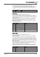
Status tables
These are word input registers reporting the conditions of all the mapped
objects. Each word corresponds with one object and is organized in two bytes:
bits 0-7 are used to represent the object operating modes. For example, the
on/off (inclusion/exclusion) conditions, whereas bits 8-15 contain the event
conditions, such as alarms, fault, and so on.
The Status tables cover the entire set of supported objects. A specific status
table is dedicated to notifications coming from objects not included in the
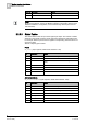
configuration. The status tables list includes:
– Panel
– Activation Mode
– Buzzer
– Communication Link
– Hardware Link
– MEA
– MDHW
– Mains
– Battery
– MCIO
– MDIO
– Functions
– Extinguishing Functions
– UGA
– BOP Evacuation Mode
– Horn
– Element
– Extinguishing Element
– Unidentified event (for objects not included in the configuration)
Compact status tables
These are available for a limited set of detection objects. The compact status