
User Manual


Modbus Interface Specifications
2
Modbus Data Model
35
Building Technologies
A6V10316242_a_en
CPS Fire Safety
31.05.2019
tables are word input registers containing a simplified status representation. In
fact, each representation is made up of 4-bit status for functions or 2-bit status
for elements. This results in 4 or even 8 objects being packet in a single word
register, thus allowing a faster acquisition whenever communication
performances have priority than status details.
The compact tables list includes:
– Functions
– Elements
Bit status tables
For extremely simple applications, a set of bit input registers is also provided
for specific objects and events that are combined in very basic 1-bit (on/off)
status report. The list of bit input registers includes:
– Panel Fault
– Activation Mode Fault
– Activation Mode Abnormal
– Communication Link Fault
– Mains Fault
– Battery Fault
– Function Safety Position Failed
– Function In Command
– Function Wait Position Failed
– Function Fault
– UGA Alarm
– UGA Activated Evacuation
– UGA Fault
– BOP Evacuation Mode On Manual
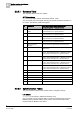
Command tables
The output command tables (read/write holding registers) enables Modbus
master/client stations to initiate control commands to the fire control panels.
Note that, depending on a configuration setting, certain commands may not be
available.
The command tables list includes:
– Panel acknowledgement
– Panel reset
– Buzzer acknowledgement
– Buzzer reset
– Function activation command
– Evacuation command
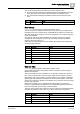
Date and Time
See Summary Table [➙ 18].
Gateway Unit Representation
A dedicated register sub-map is used for the NK823x unit, including one status
table.
Status table
This is a word input register reporting the conditions of the gateway. Each word
corresponds with one object and is organized in two bytes: bits 0-7 are used to
represent the object operating modes, for example the on/off
(inclusion/exclusion) conditions, whereas bits 8-15 contain the abnormal event
conditions, such as alarms, fault, and so on.
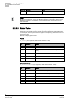
The gateway table includes the following:
– NK823x Points
– Power Supply