
User Manual


2
Modbus Interface Specifications
Modbus Data Model
36
Building Technologies
A6V10316242_a_en
CPS Fire Safety
31.05.2019
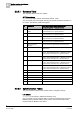
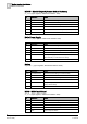
2.2.3.1 Summary Table
The Summary table includes one register.
STT20 synthesis
WT_STT20 Syn (Input register, default base address: 1000)
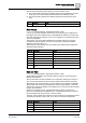
One input (read-only) word register reporting 16 general on/off panel conditions in
the 16 bits. The following relationship applies:
Bit
Information
Notes about affected objects and conditions
corresponding to the “1” state (bit active)
0 (lsb)
Evacuation manual
mode
BOP Alarm function or HLB Alarm function.
Legal information for a repeater terminal.
1
Evacuation fault
BOP Alarm function or HLB Alarm function.
Legal information for a repeater terminal.
2
Evacuation active
BOP Alarm function or HLB Alarm function.
Legal information for a repeater terminal.
3
Alarm received
BOP Alarm function.
Legal information for a repeater terminal.
4
Reset command
required
A reset command is expected by the STT20 panel.
5
Ack command required
An acknowledgment command is expected by the
STT20 panel.
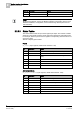
6
Function fault
Standard Function, Stop Fan function, Technical CMSI
function, Technical SDI function, or Rearming function.
Legal summary information for a repeater terminal.
7
Wait position failed
Standard Function, Stop Fan function, Technical CMSI
function, Technical SDI function, or Rearming function.
Legal summary information for a repeater terminal.
8
Security position failed
Standard Function, Stop Fan function, Technical CMSI
function, Technical SDI function, or Rearming function.
Legal summary information for a repeater terminal.
9
Safety position failed
Standard Function, Stop Fan function, Technical CMSI
function, Technical SDI function, or Rearming function.
Legal summary information for a repeater terminal.
10
Battery fault
MC20, MCO, MD20, or battery element.
11
Mains fault
MC20, MCO, MD20, or mains element.
12
Network fault
SAFEDLINK or Fire Links.
13
Activation Mode Mixed
14
Activation Mode Manual
15
STT20 Panel fault
2.2.3.2 Synchronization Tables
The Synchronization tables include a fixed number of registers. Namely:
Life Check
LifeCheck (Input register, default base address: 1010)
One input (read-only) word register that is constantly incremented as long as the
NK823x gateway software works properly and the communication with the fire
panel and with the Modbus unit is active.