
User Manual


Modbus Interface Specifications
2
Modbus Data Model
43
Building Technologies
A6V10316242_a_en
CPS Fire Safety
31.05.2019
Bit
Information
Notes
12
Wait position failed
Wait position fault
13
Fault
14
In command or
Safety position
15
Safety position failed
Safety position fault
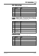
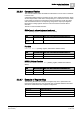
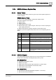
Extinguishing Element
WT_ExtElement (Input registers, default base address: 9200)
Bit
Information
Notes
0 (lsb)
Non-default mode
Abnormal mode resulting in a reduced safety
1-7
-
Not used
8
Non-default value
Abnormal condition resulting in a reduced safety
9-13
-
Not used
14
Extinguishing
released
15
-
Not used
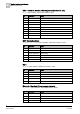
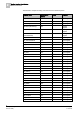
Unidentified Event
WT_Unidentified (Input register, default base address: 9300)
Bit
Information
Notes
0 (lsb)
Non-default mode
Abnormal mode coming from an object not included in the
configuration
1-7
-
Not used
8
Non-default value
Abnormal condition coming from an object not included in
the configuration
9-15
-
Not used
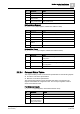
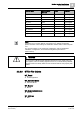
2.2.3.4 Compact Status Tables
The compact tables provide a summarized representation for the following objects:
Functions: 4-bit status representation
Elements: 2-bit status representation
The corresponding data structures, illustrated here below, are packed in the
register areas defined at configuration time. The word input registers contain 4
zones and 8 elements each.
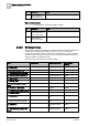
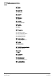
Functions (compact)
CT_Function (Input registers, default base address: 8100)
Bit
Information
Notes
0 (lsb)
-
Not used
1
Locked
2
Fault or
Wait position failed or
Safety position failed