
User Manual


2
Modbus Interface Specifications
Modbus Data Model
44
Building Technologies
A6V10316242_a_en
CPS Fire Safety
31.05.2019
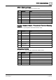
Bit
Information
Notes
3
In command or
Safety position or
Safety position failed
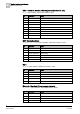
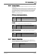
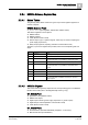
Element (compact)
CT_Element (Input registers, default base address: 9000)
Bit
Information
Notes
0 (lsb)
Fault or
Wait position failed or
Safety position failed
1
In command or
Safety position or
Safety position failed
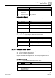
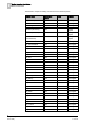
2.2.3.5 Bit Status Tables
The bit status tables (input registers) presents individual on/off event conditions for
specific types of object (Panel, Faults, Functions, and so on) and related
conditions, for example
function in command
. In each table, the value 1 indicates
that the condition is present for at least one of the objects considered. The list of
objects is defined at configuration time.
The table below collects the list of bit status tables.
Table
Information
Related object type
Default base
address
BT_Panel_Fault
Panel
10000
BT_Activation_Mode_Fault
Activation mode
11000
BT_ Activation_Mode_Abnormal
Activation mode
12000
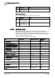
BT_ Communication Link Fault
Communication Link
13000
BT_ Mains Fault
Mains
14000
BT_ Battery Fault
Battery
15000
BT_ Function Safety Position
Failed
Function
16000
BT_ Function In Command
Function
17000
BT_ Function Wait Position Failed
Function
18000
BT_ Function Fault
Function
19000
BT_ UGA Alarm
Evacuation Control
Unit
20000
BT_ UGA Activated Evacuation
Evacuation Control
Unit
21000
BT_ UGA Fault
Evacuation Control
Unit
22000
BT_ BOP Evacuation Mode On
Manual
Evacuation Mode
23000