
User Manual


Modbus Interface Specifications
2
Modbus Data Model
45
Building Technologies
A6V10316242_a_en
CPS Fire Safety
31.05.2019
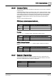
2.2.3.6 Command Tables
The command tables enable the Modbus master/client to issue control commands
to the fire units.
A read/write holding register is foreseen for each of the objects listed below. Given
an initial object state, a data value corresponding to a control action can be written
in the register to trigger the command that is then expected to modify the object
state and therefore cause a corresponding change in the object input registers.
Note that the holding registers store the code of the latest command after its
execution.
The list of command tables includes:
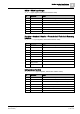
Global panel: acknowledgement and reset
STT20 (Holding register, default base address 25000)
State
Command (dec)
New state after a successful command execution
Ack required
12
Panel acknowledged
Reset
required
14
Panel reset
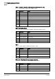
Function
Function Active (Holding register, default base address 27000)
State
Command (dec)
New state after a successful command execution
Quiet
1
Function activated
BOP/HLB Alarm Function
Alarm Function Activate Evac (Holding register, default base address
28000)
State
Command (dec)
New state after a successful command execution
Not activated
33
Evacuation activated
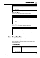
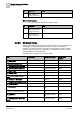
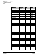
2.2.3.7 Example of Register Map
The following illustrates an example of a register map as it is presented in the
Composer configuration tool. For the panel map, the default addresses are listed
and can be customized in the Composer configuration.
Field Device
Modbus slave address
NK8237
4
FC20 Panel
5
STT20 Panel
6